Why use physical models in a learning process?
In 2016 Jo Wonjin and other researchers published in the Journal of Visual Impairment & Blindness the article ‘Introduction of 3D Printing Technology in the Classroom for Visually Impaired Students’. This articles added to the existing knowledge of the advantage of involving physical models in a learning process. We’d like to share the following excerpt to explain the added value:
Both students and teachers acknowledged the importance and usefulness of the 3D materials. The survey showed that students highly valued the 3D objects, since using them improved their memorization and understanding. Although it is still difficult to comprehend the actual size of historical relics, students claimed that the 3D materials delivered a good sense of the shapes and helped to clarify obscure meanings in the textbook.
Furthermore, the 3D materials brought liveliness and amusement to the classroom. The teacher stated that the 3D instructional materials enabled her to improve her teaching effectiveness, since the materials enriched the lecture content.
Previously, it was difficult for her to describe or explain the historical meaning behind maps or relics using words alone. Although students often felt it hard to grasp the oral explanation, they were better able to understand with the use of 3D materials. The 3D instructional materials directly stimulated the students’ imagination and reinforced their understanding and capacity for memorization. It was also effective in maintaining students’ interests during class by allowing them to touch the materials continuously.
Obtaining digital 3D models
Downloaded 3D models
Many projects start with an existing 3D model that we download from online platforms. This is often the fastest way to begin.
However, a 3D model is rarely ready to use.
- Most models are made for visual purposes
- Not for fabrication or tactile reading
- Physical use requires adaptation of models for visual purposes. This often includes reduces the details.
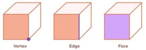
Introducing ‘the mesh’
A mesh is a digital representation of a 3D object composed of:
- Vertices (points in 3D space)
- Edges (connections between vertices)
- Faces (usually triangles or quads)
Seeing the mesh as a working material allows us to make technical decisions step by step, instead of trying to create a perfect object from the beginning.
Making a downloaded 3D model usable for 3D printing
Adapting an existing model means changing the structure of the mesh, not just the appearance. In the end, the adapted model is not only different, but better suited to its real use:
- With the goal to make the object easier to understand by touch, we focus on the tactile details which are really important.
- We simplify the geometry by removing unnecessary details.
- We keep in mind the technical capabilities of our 3D printer, to ensure a high success rate of the 3D printing process.
Indirectly, these changes often make the model easier to process for your PC.
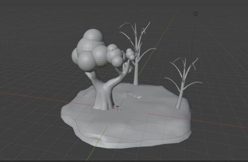
This example shows the process to obtain a scenery which shows two varieties in trees ontop of uneven terrain.
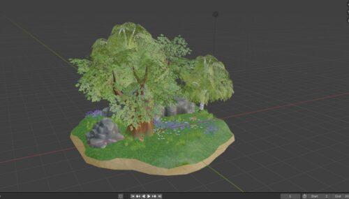
We removed rocks, plants, grass and tree leaves
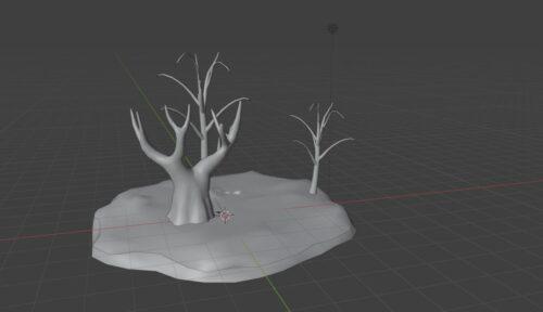
Round shapes were added to one tree to represent it’s crown.
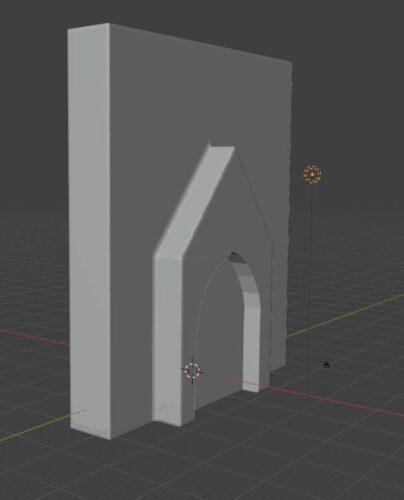
This example shows the process to obtain a scenery which communicates the difference in height between this specific church’s entrance and it’s façade.
The original model contains a large amount of arches, spires, windows and statues.
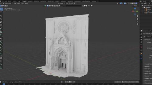
Instead of modifying the original model, we used it as a reference to create a new model:
- A rectangle was made to represent the façade
- Against the façade we added a rectangle with a pyramid on top. In this shape we created a cutout which represents the entrance.
Design 3D models yourself
When creating a mesh from zero, the shape is driven by function and physical readability, not by visual realism or decoration. The goal is to illustrate a concept.
Creating a new mesh also helps us decide which details are important. We can make some shapes stronger, remove unnecessary details, and keep the object simple.
- We start with combining simple shapes, like cubes or basic volumes. We do not focus on how the object looks, but on how it will be used.
- Step by step, we build the shape and adjust the size and proportions. This makes the object easier to understand and easier to control.
Do have a look at our 3D model database. These are optimized for 3D printing. The butterfly life cycle, found in the biology category, is a great example of the differences between reality and a tactile usable model.
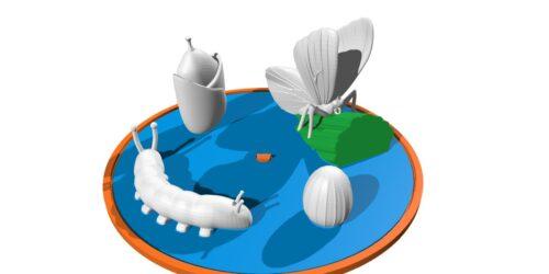
- The size of the models are larger than reality
- Accentuated lines on the egg and the leaves of the butterfly
- The catterpillar’s legs and body segments are accentuated
Do note that throughout the design process you will have to repeatedly ask feedback to the end users. This means printing a model, testing it, improving it and repeating this process a couple of times.
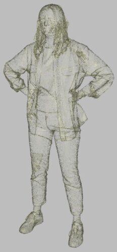
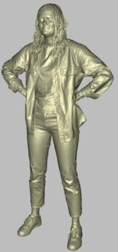
Using a real object to create a mesh
We can use tools like 3D scanning or photogrammetry to capture the shape of a real object and turn it into a mesh.
The result is usually not ready to use. The mesh can be very complex, with many small details and errors.
Therefor we must go through the same process as in the section ‘Making a downloaded 3D model usable for 3D printing’
Artificial intelligence assisted designing
We started with proving a studio photograph of a car to the AI generator.
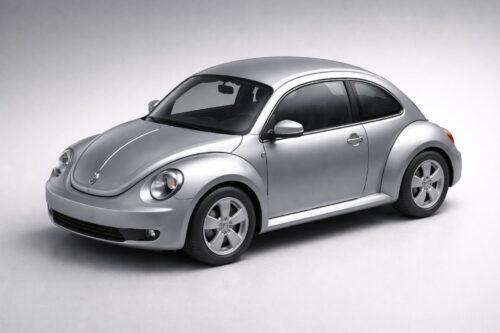
While providing the photograph you can also add more instructions. This is one of the elements which affects the 3D model generation time.
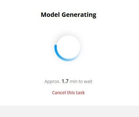
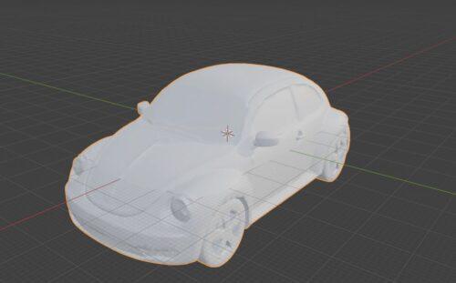
Automatic generation and AI tools can help explore shapes faster, but identical to the previous methods, the result is usually not ready to use. The mesh can be very complex, with many small details and errors.
Therefor we must go through the same process as in the section ‘Making a downloaded 3D model usable for 3D printing’
From 3D model to a physical model
If you’re not yet familiar with 3D printing, then we suggest that you read our ‘Getting started’ guidelines on this website.
In summary, the process consists out of a repetition of the following:
- Obtain the 3D model
- Specify your printer settings in its dedicated software
- 3D Print
- Test the object with the target group
- Based on the feedback, improve the 3D model