Table of Contents
As the explanations in the previous section have shown, the additional requirements for learners with a vision impairment are extremely diverse. Thus, depending on age, individual world experience and previous experience with computers, the objectives in a 3D-printing activity should be individualised. This section presents four different approaches that address different target groups. The purpose is twofold: on the one hand, we would like to present the learner with activities we have carried out in our school as part of the Erasmus+ project 3D4VIP in order to arrive at the recommendations in this report. On the other hand, we want to give you ideas that you can use as a springboard for your own activities and which you can adapt to your learning groups.
What all four of our approaches have in common is the use of OpenSCAD as modelling software because it is the most basic form of creating three-dimensional objects. Generally, software for modelling objects can be divided into three categories:
- (1) First, there are tools that basically simulate the process of pottery making. They are well suited for objects with organic shapes.
- (2) A second option is to build objects interactively from basic geometric bodies or to extrude them from two-dimensional drawings. Usually the user interfaces of both categories are graphical, which makes them unusable for people with a visual impairment.
- (3) Therefore, the third solution, text-based software like OpenSCAD, should be used with learners with no vision.
The modelling approach in OpenSCAD is based on “Constructive Solid Geometry” (CSG). This approach allows for the creation of 3D models by combining basic geometric shapes. Objects are generated by applying Boolean operations to these basic shapes.
To begin with, the modelling process is based on a text-based scripting language that describes the models. A specific syntax is used to specify the different operations and parameters required for creating the model. Unlike modelling tools mentioned in (1) or (2), OpenSCAD offers a programmatic approach to modelling. This allows for precise and parametric control over the models. By modifying parameters in the script, models can be easily adjusted and variations can be created.
The modelling approach in OpenSCAD is well-suited to creating appliances and functional models, particularly in the field of Daily Living Skills. Generally speaking, it enables efficient and flexible creation of 3D models, especially for geometrically complex shapes that may be more challenging to create using other modelling methods. Finally, it’s worth mentioning that OpenSCAD is complemented by the emerging JSCAD framework, which, however, was not considered within the scope of this project.
In order to provide you with the basic knowledge about OpenSCAD, our first activity contains additional parts with general information and basic code statements. For all activities there is a brief didactic analysis and an example of the specific code.
3.1 Building Blocks with Code
3.1.1 General Information on OpenSCAD
OpenSCAD is a free, three-dimensional modelling program that is very popular within the 3D-printing community. It can be used very efficiently for mechanical or mathematical objects (less so for figurative or art) and, with a little practice, allows a quick introduction to modelling objects, not only for programmers.
In particular, the software allows the precise positioning of objects, as all objects are easily modifiable. This is especially helpful if objects are being repeatedly optimised based on printouts. In addition, objects can be combined into components for further use.
OpenSCAD can be installed very quickly; for Windows there is a portable version that can be started directly after unpacking, in addition to a version for installation.

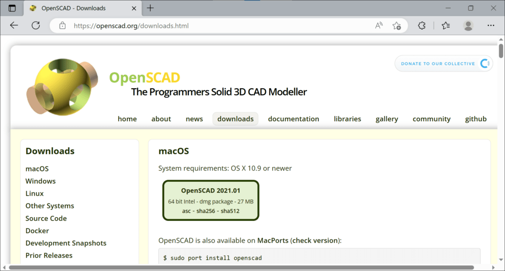
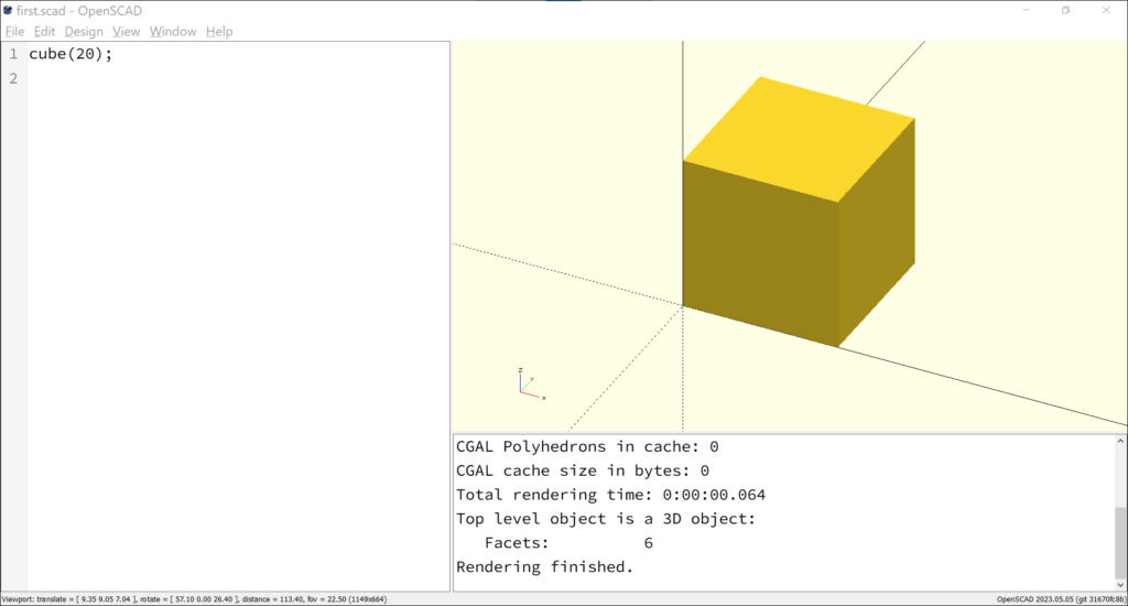
Fig. 3.1.b shows the GUI (Graphical User Interface) of the OpenSCAD application, where a minimalist layout has been chosen to provide a clear and organised working environment. The window consists of three areas: the editor (for input), preview, and console. It is important to note that OpenSCAD offers highly adjustable layout settings. Users can choose from different colour themes, disable syntax highlighting, and adjust code indentation preferences. All window areas can be accessed using keyboard shortcuts, and line numbering in the editor can be enabled or disabled, among other options. One notable feature is the ability to jump directly to program errors if the rendering process was interrupted due to syntax errors. All layout settings are stored in the registry and can be exported and imported, which is helpful when starting with a fixed configuration in a learning group.
However, using the integrated editor is not mandatory. An external editor can be useful if you want to automate the creation of multiple objects and do not require a preview. In this case, OpenSCAD can be controlled via the command line.
In the following examples we will use the internal editor. The software has undergone continuous development and the editor can now also be used with braille displays and speech output, which was not the case a couple of years ago. As soon as instructions have been entered or modified in the editor, the preview can be updated by pressing the “F5” key. Within the preview, the view can be rotated by holding down the left mouse button and moved by holding down the right mouse button. Zooming is possible via the mouse wheel. As soon as the object has been constructed, it can be prepared for printing by pressing the “F6” key. It is then saved by clicking on “File,” “Export,” “Export as 3MF…”. Other export formats are also available, however the easiest way is to export it as an STL file which can be directly initiated using the “F7” key. After making changes in the editor, we recommend you use the function keys in the following order: “F5” (error checking), “F6” (model generation), and “F7” (model export). Alternatively, OpenSCAD can be linked directly to a 3D printer using the “F8” key, either through the OctoPrint software or the printing service provider “Print a Thing.” We have not tested the printing service provider, but the OctoPrint integration can be configured to start printing directly after slicing. This appears to be the easiest method for printing as it avoids any compatibility issues with the printer.
3.1.2 Basic Code Statements
Now, let’s take a look at the code used within OpenSCAD. Each statement must end with a semicolon. For instance, the statement
// create a sphere
sphere (8);
creates a sphere with a radius of 8 mm. As you can see, the parameters are written inside round brackets and all sizes are given in millimetres. Comments are indicated by the characters “//”. It is important to note that parameters can be explicitly named in OpenSCAD, which significantly increases readability. The statement
cylinder(h=10, r=20);
constructs a cylinder with a height of 10 mm and a radius of 20 mm and
cylinder(h=10, r1=20, r2=5);
creates a truncated cone. Of course, numerical values can be multiplied, added, subtracted or divided. A library of mathematical functions is also available.
The basic objects available in OpenSCAD are cuboids, spheres, and cylinders. However, it is possible to integrate component libraries into your own designs or create your own libraries to expand the available object options. This allows you to incorporate additional shapes and components beyond the basic objects provided by default.
sphere(12);
cylinder(h=10, r1=20, r2=5);
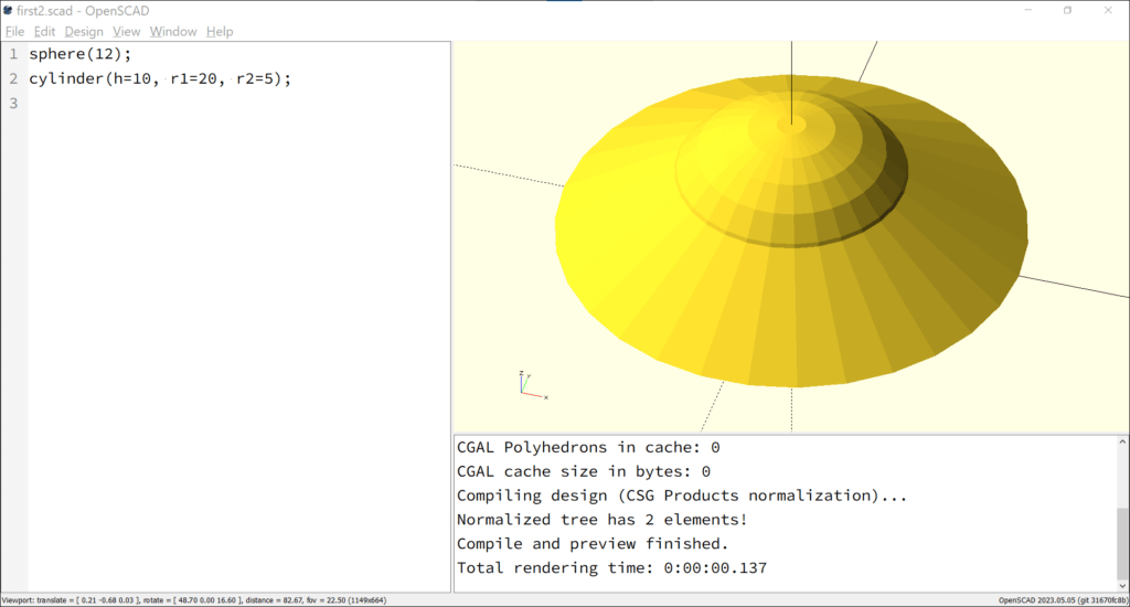
In fig. 3.1.c, the facets, i.e. small partial surfaces from which the sphere and the cylinder are constructed, are clearly visible. The surface of an object consists simply of a mesh made up of triangles. However, with the parameter “$fn” you can determine how smooth the surface is displayed. It is advisable to work with lower values at first during the construction process, as OpenSCAD can then display the objects more clearly, and only create a high-resolution surface immediately before export.
3.1.3 Didactic Analysis
Working exclusively with the three basic shapes (sphere, cylinder, and cube) is particularly suited to beginners whose spatial awareness needs further training. Just using three basic shapes also offers the advantage of creating models easily and quickly, which accelerates the learning curve. These shapes can then be combined in various ways to create complex structures, fostering creativity and allowing users to bring their own ideas to life and create their own designs. Additionally, working with these shapes is widely used in many application areas and can serve as a foundation for creating more complex models.
The next step could then be to change their size (scale) or, for example, to turn cubes into cuboids. This increases understanding of proportions and measurements, while also enabling the learners to experience a great deal of autonomy.
These self-made building blocks can then be printed and used for hands-on action. They can also be combined into new bodies on the table top. This in turn can lead to the transfer into code of those more complex bodies.
3.1.4 Example
In the following example, we will apply the modelling concept of OpenSCAD to construct a simple house, aiming to enhance understanding of the design process. The house consists of a ground floor, which is represented by a cube, and on top of it sits a cube rotated by 45 degrees, forming the roof. The upper half of this cube forms the gable roof, while the lower half “disappears” within the cube representing the ground floor, as it occupies the same space. In the side view, the model resembles a child’s drawing of a house. This description may not be immediately clear, which is why we will proceed with the construction step-by-step while providing explanations. Each individual step can be traced using the models, so we suggest you have the models readily available during group work to refer to them directly.
The following images illustrate each step, showing the inputs in the editor and the preview of the respective object. We begin with the cube that represents the ground floor of our house.
cube(2, center=true);
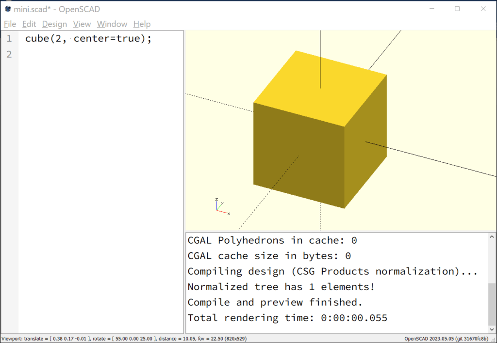
The centre of the cube is located at the origin of the coordinate system, which is achieved by setting the parameter “center=true”. A second cube is added to the first cube, which will form the future gable roof. The two commands are separated by a semicolon. This second cube is rotated by 45° with respect to the first cube.
cube(2, center=true);
rotate([0,45,0])
cube(2, center=true);
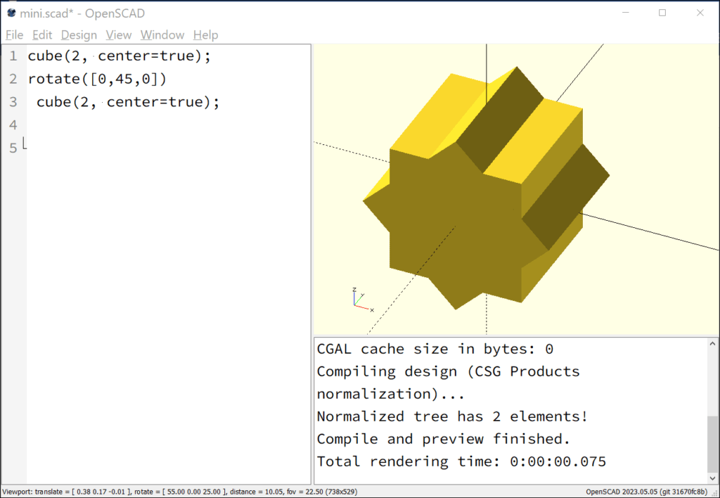
This is achieved using the “rotate” command, which is placed before the command for constructing the second cube. This is a general principle of OpenSCAD – commands are linked together by writing them in sequence. However, the execution order is reversed (in the above example, the cube is first generated and then rotated). The “rotate” command also has parameters. In this case, the rotations are specified as a vector, following the order of the x, y, z axes (in this case rotating by 45° around the y-axis). The resulting object resembles a star with eight corners.
cube(2,center=true);
translate([0,0,1])
rotate([0,45,0])
cube(2, center=true);
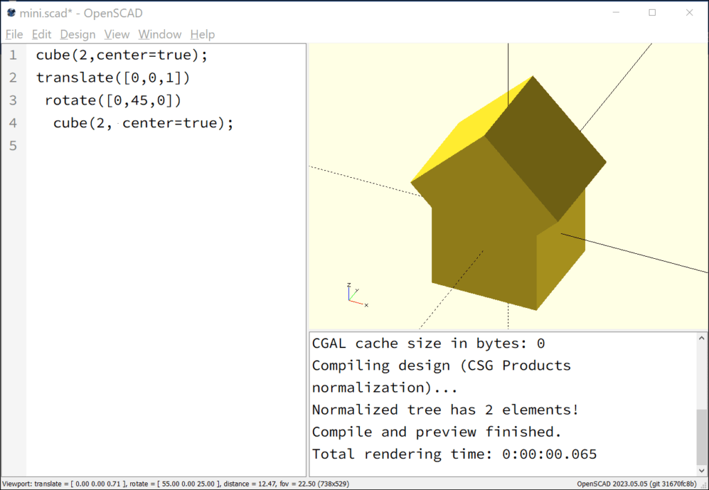
In the next step, the second cube is not only rotated but also “lifted” using the “translate” command. The “translate” command can be used to achieve translations in the three spatial directions. In our case, the cube is shifted 1mm in the positive z-axis direction. However, this translation occurs after the cube has been rotated. It is noticeable that the second cube extends in the x-direction relative to the first cube. This is because the diagonal length of the cube is sqrt(2) times wider than the edge length of the first cube. This will be corrected in the next step. To ensure that the second cube fits perfectly onto the first cube in all three spatial directions, its side lengths need to be adjusted (effectively transforming the second cube into a rectangular cuboid).
cube(2,center=true);
translate([0,0,1])
rotate([0,45,0])
cube([2/sqrt(2),2,2/sqrt(2)], center=true);
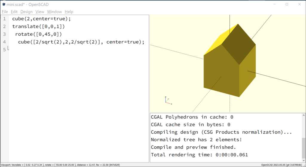
The second cube is modified so that the diagonals lying in the x- and z- directions have a length of only 2/sqrt(2). This demonstrates that arithmetic operations can be used throughout an OpenSCAD program.
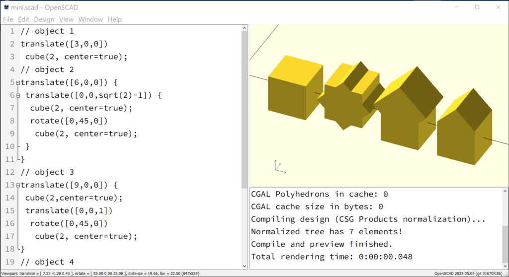
The complete program code is included in the file “mini.scad”, and the result is shown in the figure 3.1.4.e. In the filename, “1c” indicates a single-colour model suitable for a one colour print. The files marked with “2c” allow for two-colour printing when combined.
3.2 Board Game
3.2.1 Didactic Analysis
The basic idea of this activity is to combine simple geometric bodies in such a way that, when 3D-printed, they form an object that can be used in real life. Furthermore, it allows learners to create bodies of different levels of complexity, but which nevertheless serve the same purpose. Having been 3D-printed, they can then be used in a group activity.
These theoretical principles can be put into practice by making board game pieces. Since these basically consist simply of stacked geometrical bodies, they can be easily coded in OpenSCAD. In this way, simple bodies are created in no time at all, and are individually and tactilely distinguishable. Of course, learners with vision can also use other software within the activity to design more detailed pieces (for example, with BlocksCAD, which can be used online at https://www.blockscad3d.com/editor/). Creating game pieces offers the full design range from easy to difficult and from simple to intricate, making it suitable for different skill levels. Due to the relatively small size of the pieces, they can also be printed quickly, making success tangible for the learners.
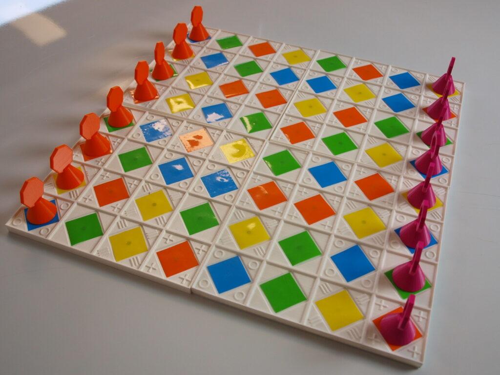
To embed the activity into a larger context, we decided to create a Katarenga game set. This board game is related to chess, but only has one type of piece in each colour (eight pieces per colour). (It is not the shape of the piece, but the colour of the square on which the piece stands that dictates which move may be made next). The task is then to design a piece according to one’s own ideas and abilities, and the only restriction is that it must remain distinguishable from the opponent’s pieces afterwards.
A possible extension of the task would be to have both types of figures (i.e. player 1 and 2) created by the same learner. This might help to encourage a more differentiated view of the pieces. Again, it is important that the pieces are clearly distinguishable from each other both tactilely and visually despite their similar design. An example of this task is shown in the following figures:
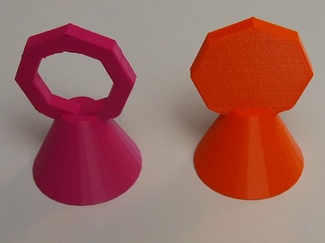
Here, two pieces with similar designs were created, but different textures and colours were used to distinguish them from each other. Using different materials and textures makes it easier for people with a vision impairment to distinguish the pieces tactilely, while using different colours makes it easier for sighted players to distinguish them visually. This approach also encourages the learners’ artistic creativity.
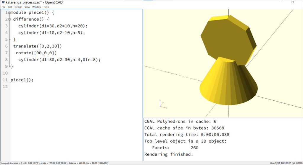
The example shows the work of a learner. The result of the code examples is illustrated in the two screenshots. One screenshot shows a game piece with a solid cylinder, while the second piece resembles an octagonal ring. The two figures were made distinguishable with a cut-out, where the piece is usually picked up. Basically, the figures consist of a truncated cone onto which a horizontally aligned cylinder is placed centrally. The cylinder is closed in figure 3.2.c, and it has an opening in figure 3.2.d. This gives the cylinder the shape of a ring.
Another option for learners within the group who have a lot of experience could be to design the board so that the individual squares are tactile and the colour codes are translated into tactile markers. However, if there are no learners for whom this task is appropriate, the tactile board should be made by the educator so that the pieces can then be used in an actual game.
(Of course, many other games are also suitable for this activity.)
3.2.2 Example
The piece created in OpenSCAD after a few development cycles and corrections to create the two pieces reads as follows:
module piece1() {
difference() {
cylinder(d1=30,d2=10,h=20);cylinder(d1=10,d2=10,h=5);
}
translate([0,2,30])
rotate([90,0,0])
cylinder(d1=30,d2=30,h=4,$fn=8);cylinder(d1=30,d2=30,h=4,$fn=8);
}
module piece2(){
difference(){
cylinder(d1=30,d2=10,h=20);cylinder(d1=10,d2=10,h=5);
}
translate([0,2,30])
rotate([90,0,0])
difference(){
cylinder(d1=30,d2=30,h=4,$fn=8);cylinder(d1=20,d2=20,h=4,$fn=8);
}
}
piece2();
The two pieces were designed separately as piece1() and piece2(), and in the last line of code the piece2() module is called up to create the second piece. In this particular piece, the construction of the ring is interesting. It is created by taking the difference between two cylinders: a slightly larger one from which a smaller one is subtracted. This is done using the “difference” command. (For more details on commands please see 3.1.1.)
3.3 Soma Cubes
3.3.1 Didactic Analysis
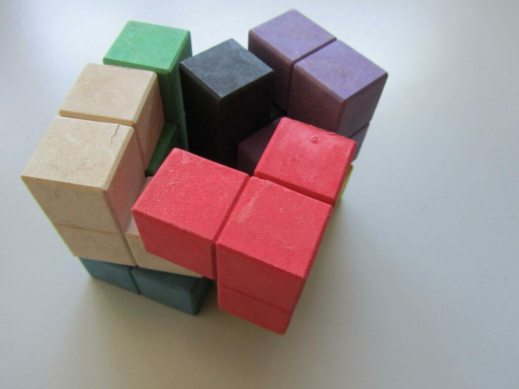
First of all, we should explain the concept of Soma cubes: the Soma cube (fig. 3.3.a) is a 3D jigsaw puzzle that can be assembled to form a cube consisting of 3x3x3 small cubes. The Soma cube consists of seven building blocks, which can be arranged in 240 different ways. Each of them looks like a 3D-Tetris piece that is made of four adjacent cubes. Basically, there are seven pieces. If you leave out the two simple shapes, where the four cubes are in a straight line, or in rows of 2×2, there are six shapes left. Additionally, there is one bent shape consisting of only three cubes, which makes it seven in total.
The didactic peculiarity of Soma cubes lies in their being an excellent pedagogical tool to promote spatial awareness and construction skills. By solving this construction task, cognitive abilities such as problem-solving, spatial awareness, fine motor skills, and logical thinking are fostered. Soma cubes offer a practical and interactive learning environment that can help learners understand abstract mathematical concepts and engage creatively with geometry. Moreover, Soma cubes can also be used as a tool for the development of social and emotional skills, by providing learners with the opportunity to collaborate in solving complex problems and sharing solutions.
It is also possible to print various intermediate stages of Soma cubes to use as a guide when constructing the cube. The individual pieces of the Soma cube can also be used to create other shapes, for example a sofa. By engaging in group activities where the printed Soma cubes must be solved within a certain time frame, further activities can be developed to promote social learning goals as a project conclusion.
3.3.2 Example
But enough theory, let’s construct one part of a Soma cube – a T-brick – with OpenSCAD. We’ve chosen a cube with an edge length of 16 mm as the basic building block.cube(16);
For the T-brick (the four cubes are positioned relative to each other in such a way that they form the shape of a capital “T”. Keep in mind that learners with no vision cannot relate to this description as the braille letter T looks completely different.) we need several cubes. Since these are all created in the origin of the coordinate system, we have to translate the cubes with the instruction
translate([x, y, z]);
to move them to the desired position.
module t_brick() {
cube(16);
translate([20,0,0])
cube(16);
translate([40,0,0])
cube(16);
translate([20,20,0])
cube(16);
}
t_brick();
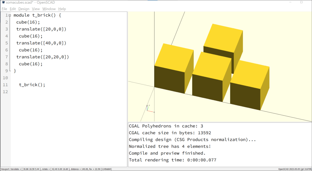
It is advisable to combine the four cubes into a single object using the “t_brick” module since they are logically connected. However, there are still 4mm gaps between each cube. We now want to close these gaps in a way that the transitions between the cubes don’t completely disappear but remain tactilely distinguishable, making it easier to understand how the object was formed. To do this, we will use the “minkowski” command, which applies one object onto another in the following way: the first object is overlaid with the second object by being applied to its entire surface. For example, if a cube is overlaid with a sphere, the sphere is rolled onto the entire surface of the cube. The resulting object still has the shape of a cube but with rounded corners derived from the sphere.
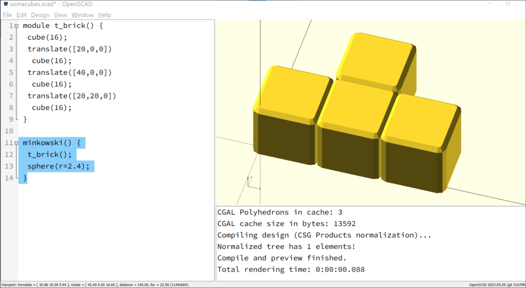
minkowski() {
t_brick();
sphere(r=2.4);
}
In our example, it is sufficient to apply “minkowski” to the “t_brick()” module. The result is shown in (fig 3.3.c).
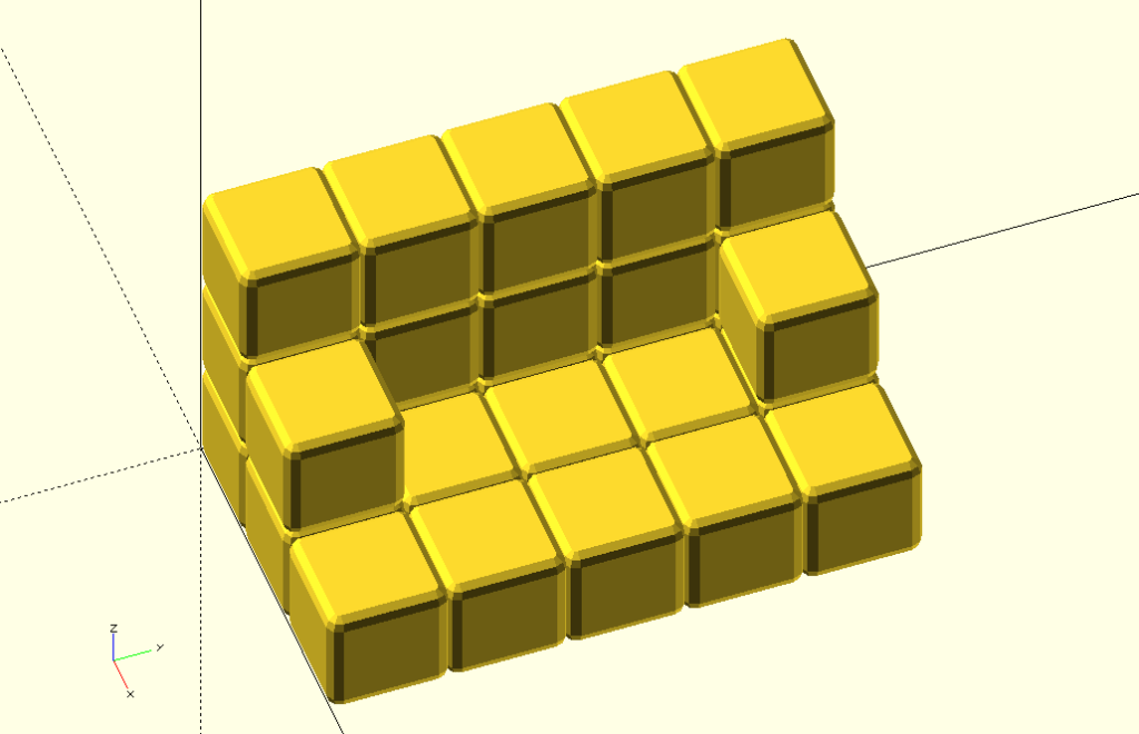
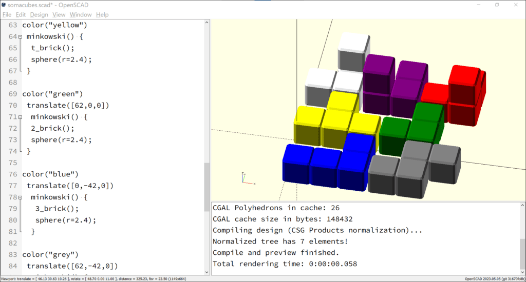
The other six building blocks of the Soma cube can be constructed in the same way (see file “somacubes.scad”). They are exemplified in the figure (fig 3.3.d).
The functions shown only give a first impression of the possibilities available when modelling with OpenSCAD. Another important function is the extrusion of two-dimensional drawings, rotations can be carried out as well as reflections, etc. The objects created can be combined with each other. However, it is also possible to subtract them from each other to form intersections, etc.
3.4 Miniature Block Worlds
3.4.1 Didactic Analysis
Construction with blocks in Miniature Block Worlds is based on the principle of virtual blocks, each occupying a certain space or volume area that can be surrounded by other blocks. The unique quality lies in the fact that the virtual boundaries of all the blocks used have the same measurements, regardless how much of it is filled with material. These blocks can be used to create buildings, landscapes and many other things. Learners can stack blocks to form walls, towers, or other structures, or they can arrange them in specific patterns to create complex objects. Construction with blocks offers learners incredible freedom and creativity in designing worlds and exploring ideas.
Besides creativity, it fosters problem-solving strategies and spatial awareness, and enables learners to test and experience mathematical concepts. By creating replicas of historical buildings or landscapes they can even learn about and understand history and culture in a creative way.
Being closely related to the core concept of the popular video game Minecraft, it also offers a special benefit for learners with a vision impairment: working with the 3D-printed blocks of those miniature worlds, they can get an idea of the fascination that their sighted peers have with this video game.
3.4.2 Example
The illustration (fig 3.4.a) shows an OpenSCAD screenshot. On the left hand side of the application the commands are explained and applied to construct a miniature block world. The right hand side of the window shows the rendered model.
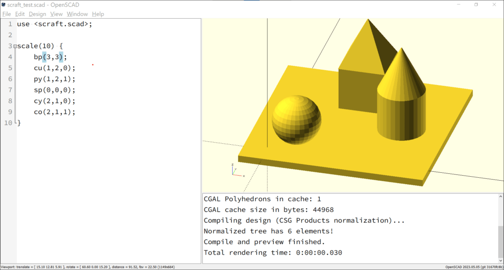
The model has a square base. On this base, near the origin, there is a sphere. One could imagine this sphere as a spherical tree in a landscape model, for example. On the model, there are two additional elements that resemble buildings. One has a cylindrical base with a conical roof, while the other is square with a four-sided pyramid on top. The corresponding program code is as follows:
use ;
scale(10) {
bp(3,3);
cu(1,2,0);
py(1,2,1);
sp(0,0,0);
cy(2,1,0);
co(2,1,1);
}
To keep the input as compact as possible, the individual module names are the first letters of the objects listed:
// bp: Base plate
// cu: Cube
// cy: Cylinder
// py: Pyramid (4-sided)
// co: Cone
// sp: Sphere
// gr: Grass
// sa: Sand
The parameters used are the front-bottom-left corner coordinates of the corresponding object. For example, the input “sp(0,0,0);” defines a sphere with its front-bottom-left corner at the origin. The back-top-right corner of the sphere would then be located at point (1,1,1). This describes the spatial range of a cube that encloses the sphere and has a side length of 1mm. To define a reasonable size for the output, all objects are scaled up by a factor of 10 using the “scale” command. In this project, it is advisable to start with the default objects. More complex objects can be added to the “scraft.scad” library as desired. To use the library for your own project, it needs to be included using the statement “use ;”. The file should be located in the same folder as your own project file. The commands are contained in the file “scraft_test.scad”, which can be edited with any text editor or directly in OpenSCAD. The miniature block world example is available as a printout and can also be displayed on a PC with the Cura program. To do this, open the file “scraft_test.stl” or simply create your own worlds.
With the combination of the library and the built-in features of OpenSCAD, there are many more possibilities to create your own models. It may quickly become apparent that manually placing objects as described can be quite cumbersome. One way to speed up the construction process is by using loops.
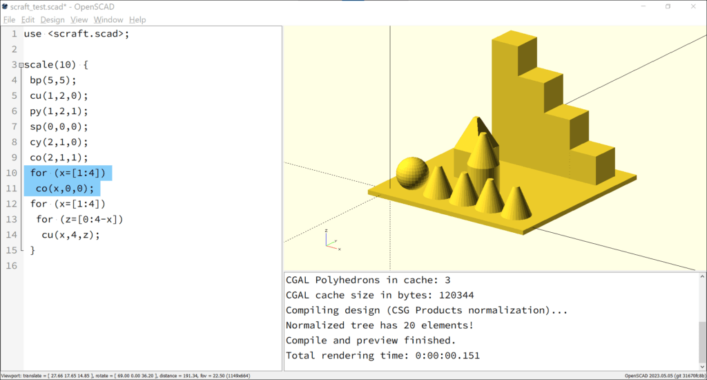
This example demonstrates how the previous model was extended with two additional structures. The result is shown in (fig 3.4.b). The corresponding program code is as follows (to be used within the “scale” block):
// A row of cones
for (x=[1:4])
co(x,0,0);
// A staircase made of cubes.
for (x=[1:4])
for (z=[0:4-x])
cu(x,4,z);
By using a for loop, the individual objects are generated multiple times. In the first case, for example, a total of 4 cones are created. Loops can be nested, as in the second case, allowing objects to be assembled in multiple spatial directions. For those who want more, there are options of working with conditions, scaling, mirroring, and other techniques to further expand the possibilities.


tactiles.eu has been produced by the 3D4VIP project co-funded by the Erasmus+ programme of the European Union