Clearing the environment
When you open Blender, by default, the software will automatically create a small test scene with a box, a camera and a light source. We are not going to use these so you can delete them as follows:
- Press “a” on the keyboard to select all objects in the scene.
- Press “del” to delete all selected objects.
Creating the shape of the dot
Now can start to create the shape of a braille dot.
In an empty file:
- Press “Shift+a“. This opens a context menu where you can select the type of object you want to create.
- Select UV Sphere.

Blender will create a UV sphere wherever you have the 3D cursor and this will be the origin point (0,0,0).
You should see something like this:
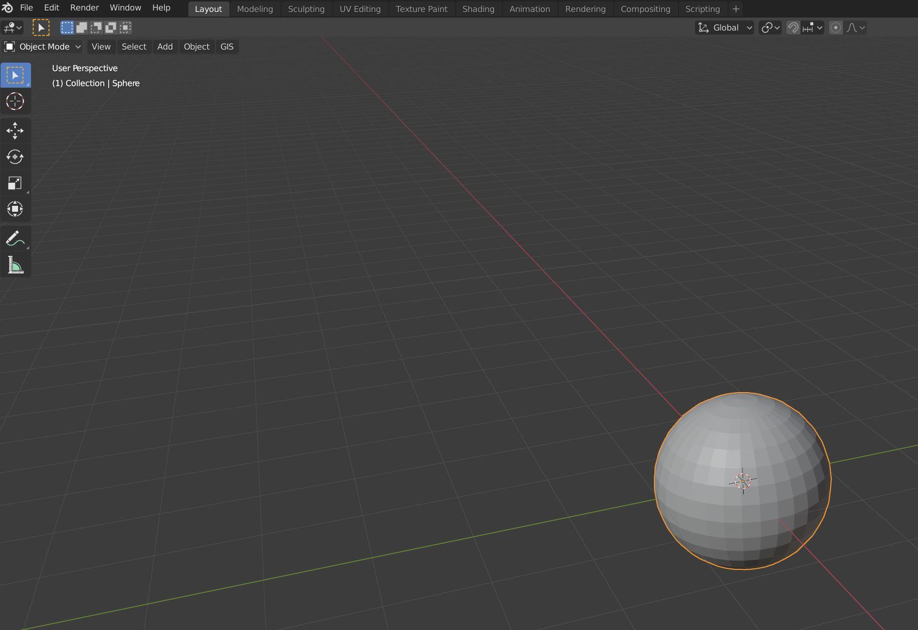
At the top left of the screen you will see a dropdown menu called “Object mode”. This is the standard mode to select objects on the screen and perform some basic manipulations such as moving, rotating and scaling.
Now let’s remove the lower half of our sphere. In order to do that we need to edit the sphere mesh. That means changing from “Object mode” to “Edit mode”:
- Ensure your sphere is selected (as in the above image).
- Enter “Edit mode” in one of the following ways:
- Press “Tab” on your keyboard.
- Go to the “Object mode” dropdown menu and select “Edit mode”.
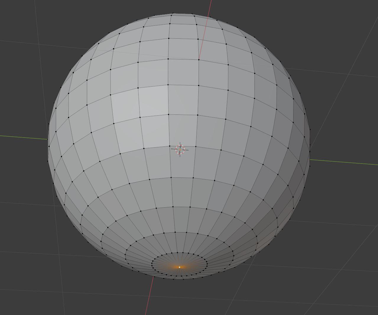
The sphere should now appear as in the following image:

In Edit mode you can select the vertices, lines or faces of the meshes you have chosen. To change the component selected, press one of the three buttons to the immediate right of the dropdown menu that now says “Edit mode”. Choose “vertex select” (as in our previous screen).
Let’s select the vertex at the bottom of the UV sphere.
Then press the “Ctrl” key and the “+” key to select the adjacent vertices until you have selected the entire lower half.
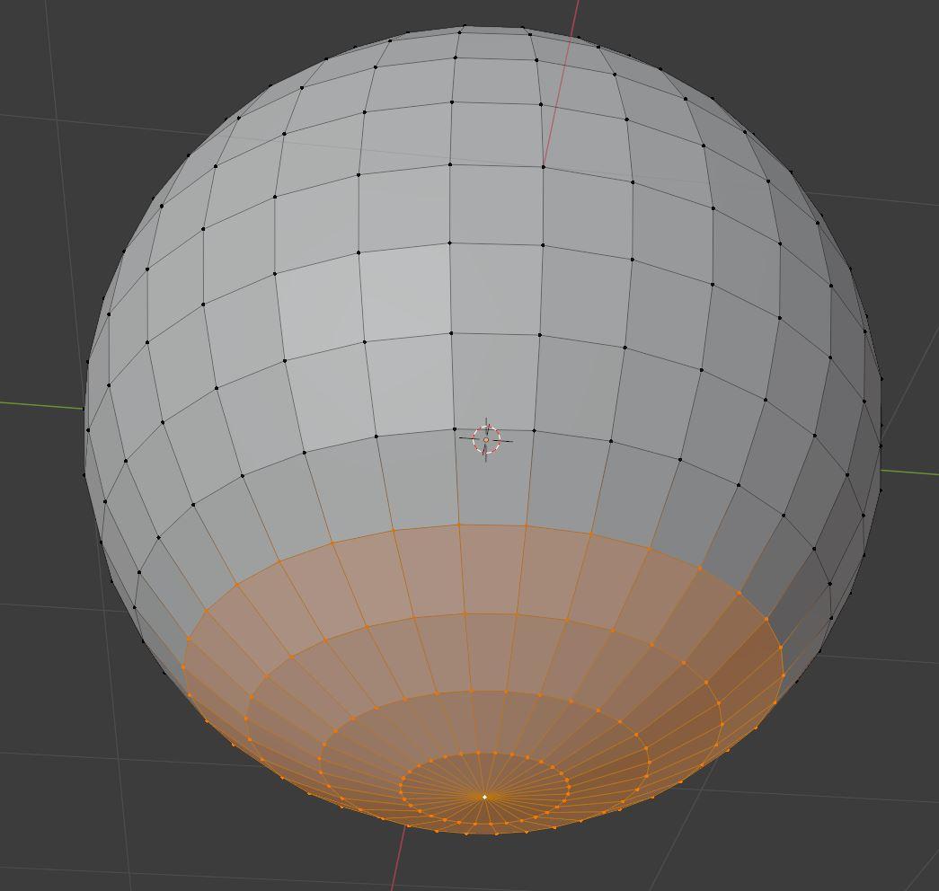

Now press “Del” and select the option “Faces” from the context menu because we only want to delete the selected faces.
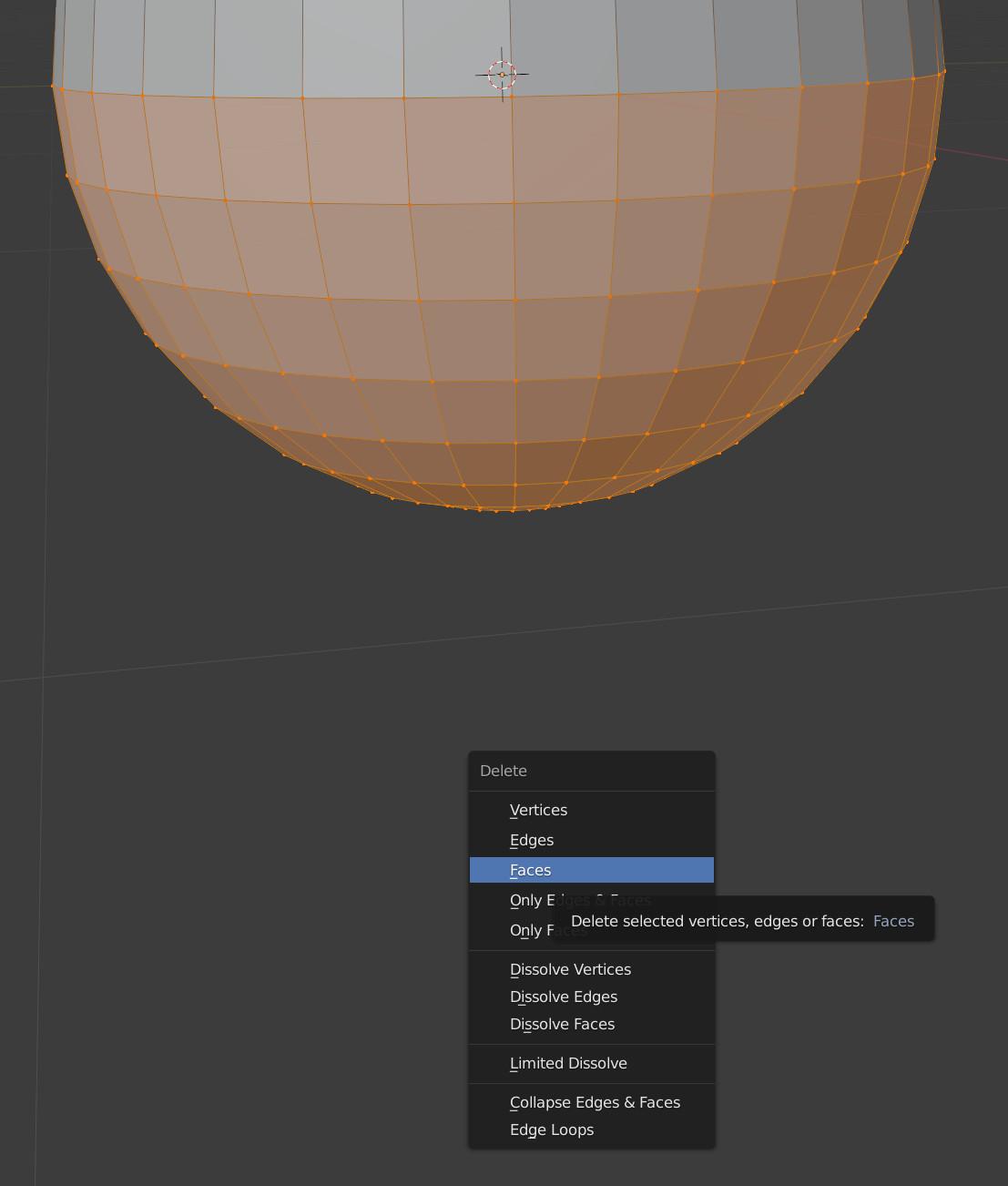
Return to “Object mode” by pressing “Tab“. This is what you should now see:

Setting up units and dimensions
If you want to check the current size of your object, press “n” on your keyboard and the sidebar will appear.

As you can see, our object is 2 metres by 2 metres by 1 metre.
For better readability, let’s change the units to cm.
Go to Scene properties, then Units, Length, and select centimetres:

Your length measurements should now change to cm.
As we are going to be working with very small distances, let’s change the clipping distance. Go to the sidebar, select the View tab and change Clip Start from 10cm to 1cm, or smaller if you experience any issues trying to move the camera closer to the object.

Now, with the sphere selected, you can enter the measurements in the sidebar. For this example, we have decided to use
x: 0.14, y: 0.14, z: 0.07
Zoom in with the mouse wheel and you should be able to see the object:
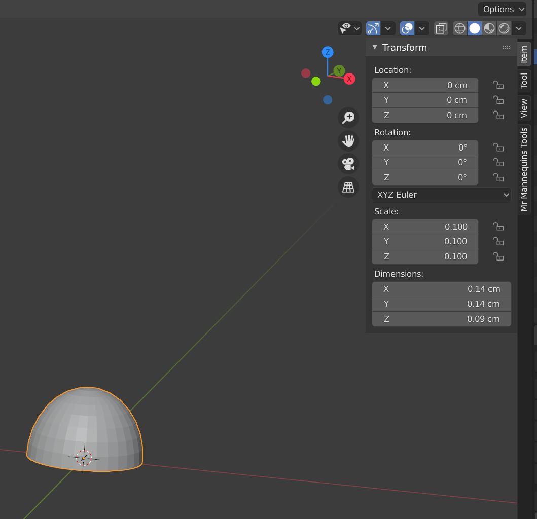
Although this dot appears finished, remember we scaled the object but we didn’t apply the scale to its original shape (the scale factor in the sidebar is not 1,1,1).
As there will be further steps with modifiers, let’s apply the scale. Press “Ctrl+a“, and select “Rotation and Scale” or simply “Scale” from the option list.

Now the scale factor in the sidebar should be (1,1,1).
Creating the remaining braille dots
Go to the Modifier Properties tab.
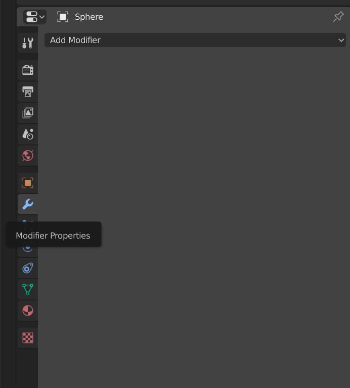
Select “Array” and set up the following elements of your new modifier:
- Keep the Count at 2 because we only want two dots in the x-axis.
- Deselect “Relative offset”.
- Select “Constant offset”.
- Set the x-axis to 0.23cm, which is the distance between the centre of the two dots.

Please bear in mind that if you didn’t apply the scale, the constant offset will also be affected by that scale which is not what we want in this case.
Let’s create the remaining dots with another Array modifier:
- In “Add modifier”, select “Array”.
- Set Count to 4 because we now want four dots in the y-axis.
- Deselect “Relative offset”.
- Select “Constant offset”.
- Set the y-axis to 0.23cm which is the distance between the centre of the two dots.

Finishing touches
If you want to improve the smoothness of your dots, you can do the following two things:
Smooth normals by right clicking on the object with the mouse and selecting “Shade Smooth”.

Increase geometry by going to the Modifiers tab and selecting the Subdivision surface. Then you can select how much you want to subdivide each face. The result should look something like this:

Exporting to STL
Go to File, Export, Stl (.stl)

One of the problems with exporting to STL in Blender is that the measurements you entered for editing the scene are not retained when exporting. As a result 1 Blender metre = 1 Blender unit = 1mm in the Stl file. For that reason, after selecting the location where you want to save the file, also set up the following configuration in the save screen:
- Scale: 1000
- Scene Unit: checked

Finally, press “Export STL”.