If designing a model for visually impaired learners, lines must be tactilely distinguishable. The most fundamental rule is that each line must be designed or printed in relief and not be recessed.
Dimensions of the lines
It is sufficient to design a raised line as a simple block extrusion. It is unnecessary to round off the edges, as this is achieved to some extent by the printing method of FDM printers.

Tactile lines can be traced from a height and width of 0.5 × 0.5mm. However, there is a problem. Lines on a vertical outer side of a model, which are thinner than the built-in nozzle of the printer, are ignored by the slicer. To speed up printing times nozzle sizes up to 1.0mm are often used. For that reason a line of 1.0mm in height and 1.1mm in width has advantages, as it can be flawlessly printed by nozzles of every size.
Differentiation of various line symbols on a model
Many prints require the application of different line types on the same model, all of which have to be clearly differentiated from each other. The structure and dimensions of these lines must therefore be distinct. In addition to the standard line (continuous 1.0 × 1.1mm), other line types are also described below.

Dashed line
This line has a width and height of 1.0 × 1.1mm but consists of many individual strands. Every strand is 7mm in length, followed by a break of 3mm.

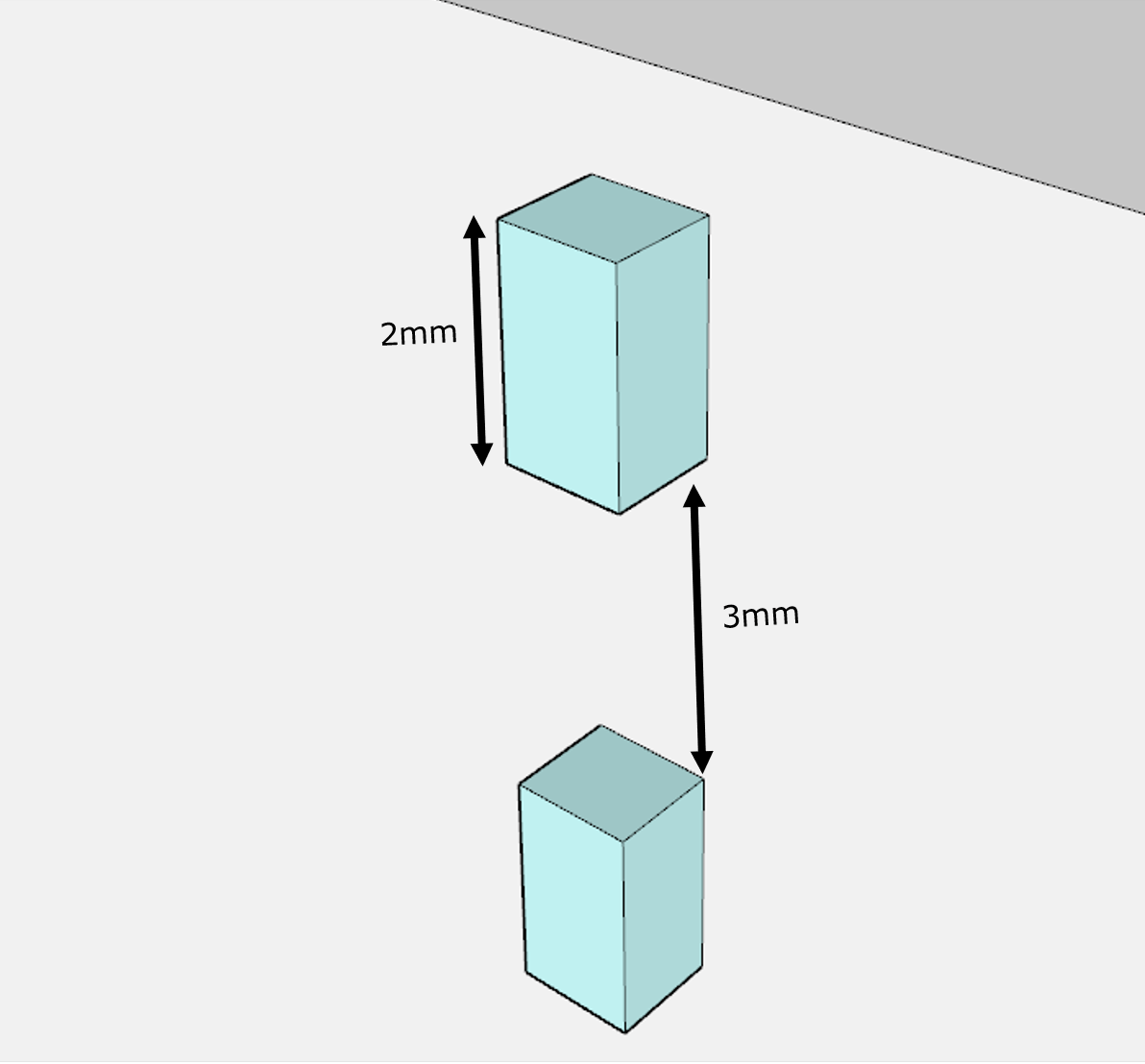
Ultrafine dashed line
The ultrafine dashed line has a width and height of 1.0 × 1.1mm. However, it consists of 2mm long strand, followed by 3mm breaks.
Other dimensions
Two solid lines are distinguishable from each other if they clearly differ in their dimensions. If an additional line is constructed with a width of 2.0mm and a height of 0.5mm, this is readily distinguishable from our standard continuous 1.0 × 1.1mm line. Nevertheless, this line type should only be used after the two dashed line types have already been used and a third line type is needed.
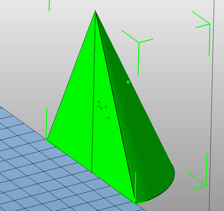
Lines inside a model
Drawings for sighted people often have an invisible outer shell, so that lines inside the model are also visible (for example, the height of a pyramid). In a 3D printed model, such a line can only be felt if the model can be divided into several subparts. In this case, a folding model consisting of two halves is preferable. After printing, the model is fastened together with adhesive tape in such a way that a hinge is created. The model can be unfolded and folded when being explored.
Lines on the base of a model
Cable tie
Lines often need to be printed on the base of a model. If the model cannot be rotated for printing because it contains braille or similar structures, a notch is printed on the base of the model. A cable tie (1.2 × 3.5mm) is then glued inside the notch. This cable tie is to provide a raised line on the base.
The groove is constructed with a width of 1.4mm and an additional offset of 0.2mm in width on either side (one layer thickness deep) at the groove edges to the print bed (optional for better print results without post-processing). The depth of the groove is 2.5mm so that the cable tie described above can be inserted and then glued on with adhesive.

To prevent the cable tie from sticking out of the model at the object’s edges, grooves should be placed 1.5mm from the outer edges. In this way the edge of the model is not interrupted by the groove or by the cable tie inserted later.

Unprinted filament
As well as the option of the glued-in cable tie, the use of unprinted filament makes a lot of sense. A recess is constructed in the base of the model into which a piece of filament is glued after printing. The recess should be semi-circular and have a diameter of 2mm so that 1.75mm thick filament fits in well.

Cutting in half
Often a model, if it is awkward to print as a whole, can be divided into two halves by a cutting plane. This is usually possible in the slicer. The cut surfaces of the two halves then form the first layer and lie directly on the printing plate. These layers should be printed as thin as possible (one or two layers are enough) to avoid warping.

Minimum distance between two lines
It’s good practice to keep a minimum distance of 2mm between two lines. Despite this, it may still be necessary for lines to intersect. The closer two lines come to one another, the more important it is to make them clearly tactilely distinguishable.