Hinges can be created directly in some 3D drawing programs, but this is not possible with all software. Moreover, these hinges may be not be optimised for 3D printing.
Hence, this tutorial will take a universal approach. Durable hinges can be created which are also easy to print. By using a nail as a pin, the hinge also offers very good stability.

Designing in 2D
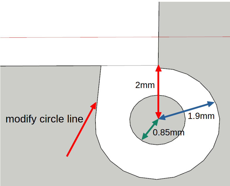
A hinge should be designed in two parts at the corner of the two models you want to connect. From the corner of the model, the centre of the bolt (red line in the diagram below) is offset 2mm to the outside. From there, a circle with radius r = 0.85mm is drawn. This is followed by a larger circle (blue line in the diagram below) with radius r = 1.9mm. To give the hinge more stability the circle line is modified as shown in the figure.
Obviously, the two base surfaces of the hinges should be drawn on both parts in order to be connected at the corresponding points.
Dimensions
Special case: font, lines, dots or similar between folded surfaces
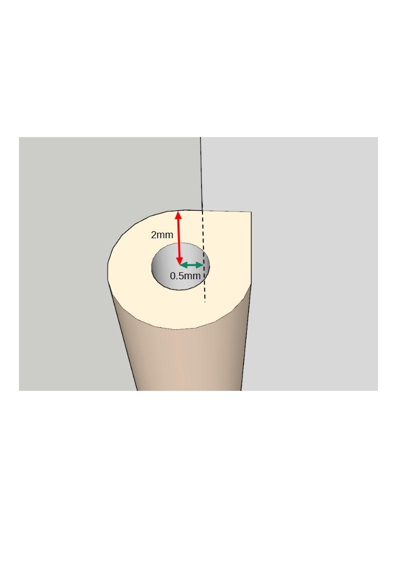
If the model contains raised parts such as braille or lines between the folded surfaces, the dimensions given above will not fit. The problem being that the model cannot easily be closed. In this case, the centre of the circles should be set 0.5-0.8mm outside the extended edge. The following figure shows the principle clearly.
Construction in 3D
In the last section, we explained how to construct the footprint of the hinge. In the next step, this footprint must be transferred into three dimensions – i.e. extruded. Here it should be noted that s must be made. The two parts of the hinge are alternating. Usually, 5-part hinges are suitable, whereby the middle part can be significantly longer. A gap of about 0.2 – 0.3mm should be constructed between the cylindrical parts.

Printing
It might be advisable to use a support structure in order to bring the individual parts together here. Further details can be found in article on support.
Assembly of the hinge
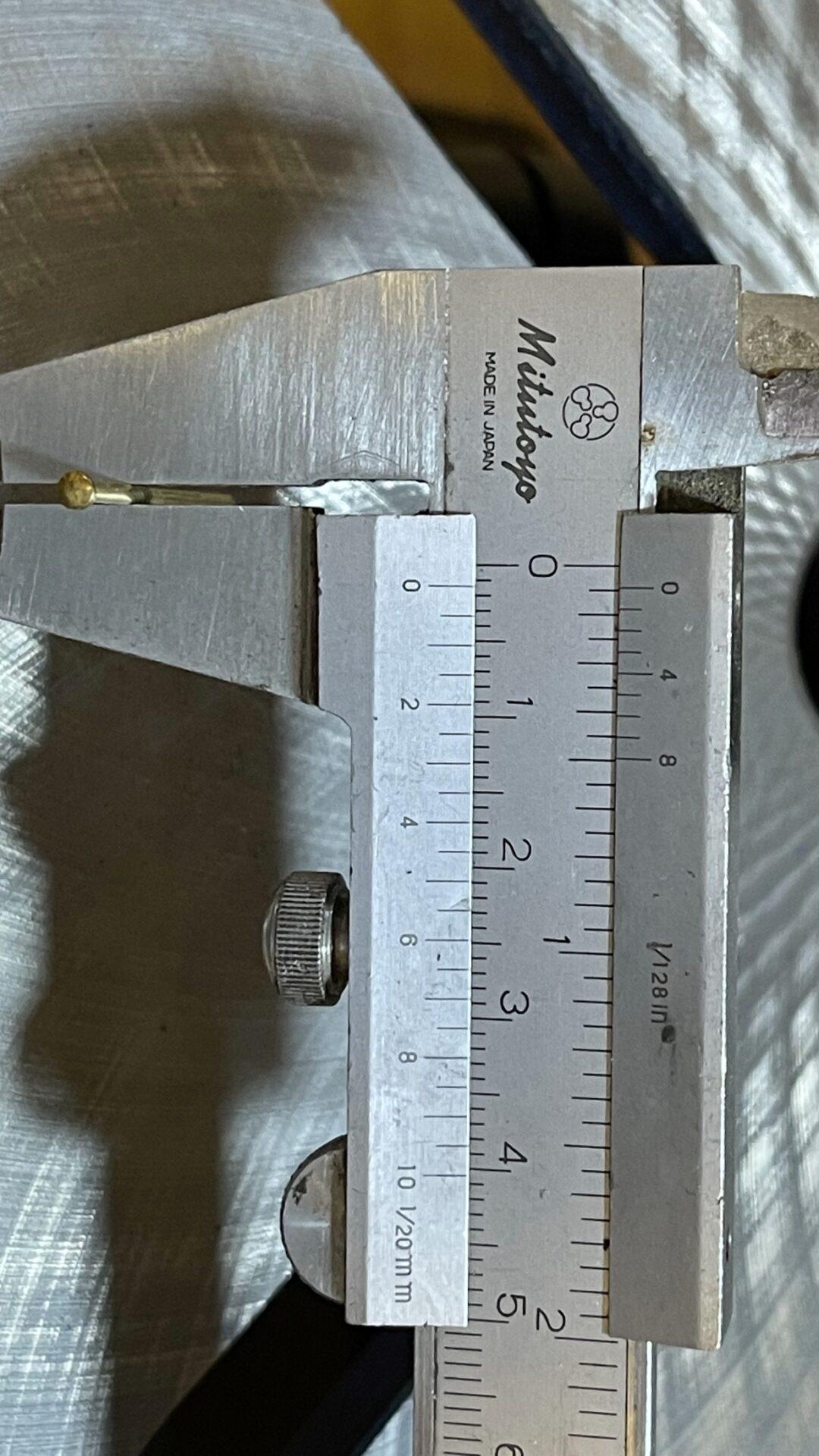
As the hinge will be permanent, the last step is to insert the pins. A nail with a diameter of 1.4 mm (the head cut off with pliers) has been found to be the most suitable solution for this. To further stabilise the connection, the nails should be glued into one part of the hinge with superglue.
Customise hinges without assembly in OpenSCAD
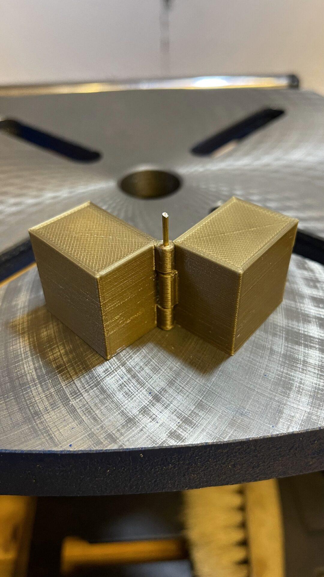
Hinges can also be printed directly, eliminating the need to assemble them in a second step. This is possible, for example, with an OpenSCAD script, with the help of which the desired hinge can be created according to preset parameters. Settings such as length, width, diameter, number of hinge elements etc. can be adapted to the user’s needs. The illustration shows an example where a hinge connects two cuboids.

Created in this way, the object can be printed “in one piece”. If water-soluble support can be printed, then support should be placed in the joints. Otherwise some force is needed initially to set the hinge in motion. The amount of support needed between the different parts is minimal, as you can see in the next two pictures (support in light blue).