As a rule, models for 3D printing are designed as solids that do not have a predefined wall thickness. For example, if a cube needs to be designed and printed, it is constructed as a “solid” cube in the design software. Only the outer walls are defined, resulting in a closed outer shell.
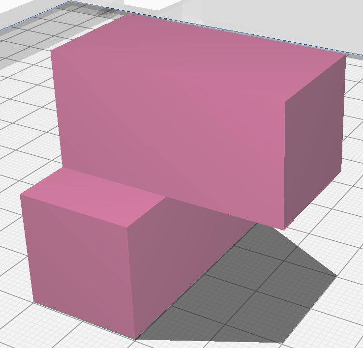
The combination of cuboids hown below, for example, should not be printed as one massive body.
A thin outer shell of about 1.2mm is usually sufficient for stability. This means that less material is needed, which makes the model cheaper and the printing process takes less time.

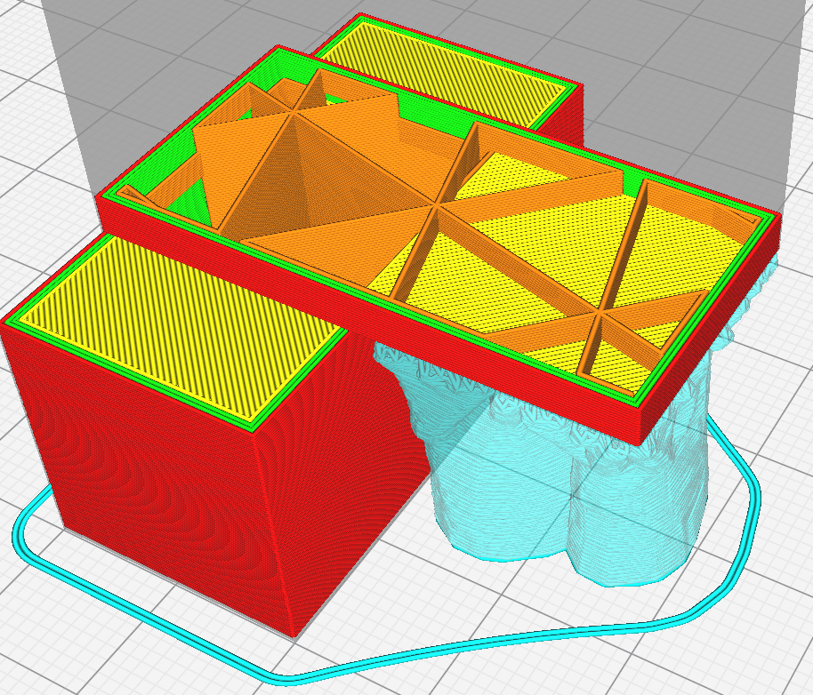
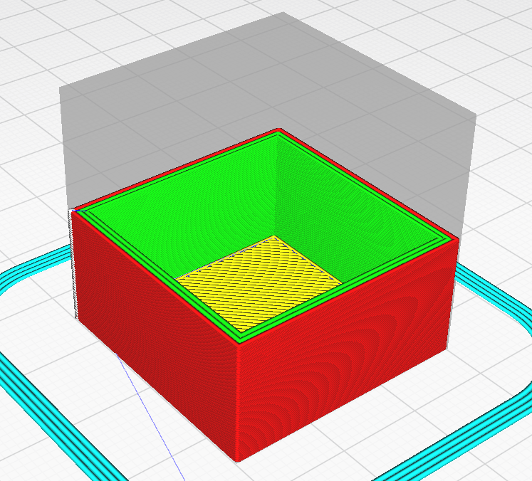
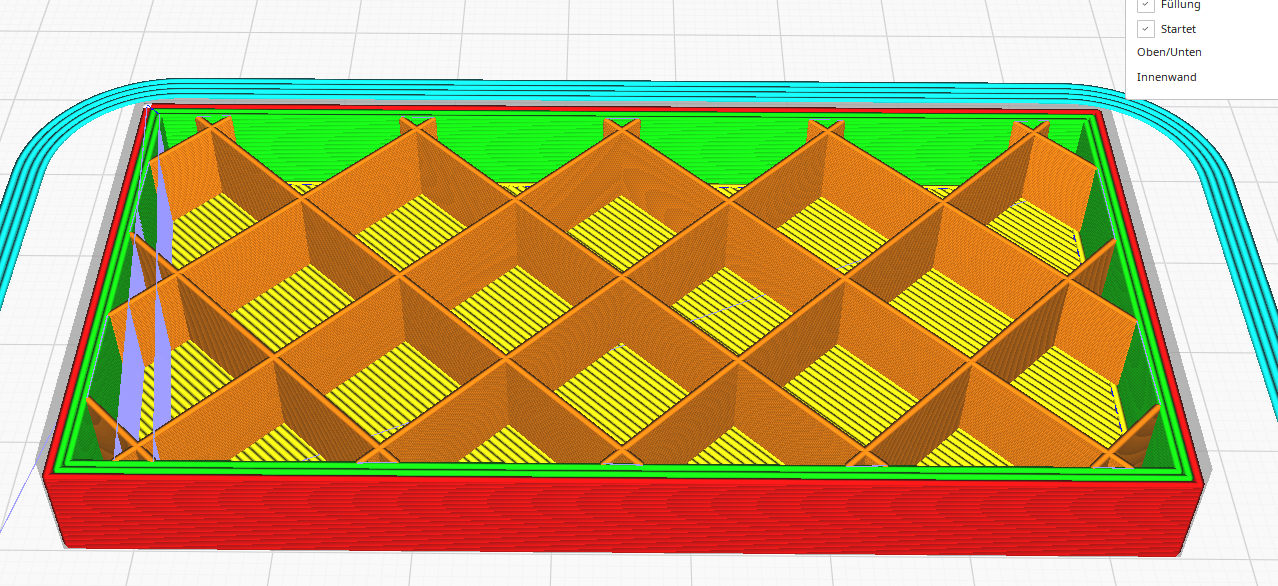
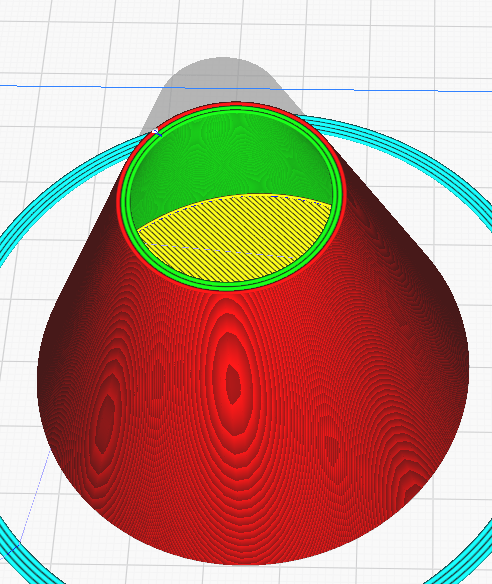
In this and the following images, the outer walls are shown in red, the inner walls in green, bottom or top surfaces in yellow and support surfaces in blue. There is no infill (orange): the model is hollow.
Hollow 3D prints are not suitable for a whole range of models. There are two reasons for this:
- Stability
The stability of a model (without taking into account the type of filament) results from its geometry, size, wall thickness and the infill. These factors influence each other. For example, if the size increases, it usually needs thicker walls and more infill. If a model has insufficient stability, it can quickly break under load.
- Printing process
In the printing process with a typical fused filament 3D printer, individual layers are applied one after the other. If a model is printed hollow, the uppermost layers have no support and can collapse into the model. This problem varies in intensity depending on the quality of the printer. Shorter distances can easily be bridged by the print head. The problem can also be reduced by increasing the quantity of top layers.
If the stability of the object is not important, an infill (Cura: Lightning) can be created simply to ensure that the top surfaces of the model are printed cleanly.
Unfortunately for these two reasons, many models cannot be printed hollow. But since solid objects are not the solution either (printing time, cost, tension in the material), percentage infill is the perfect middle ground between a solid and hollow object.
The infill is only inside a model and is no longer visible after printing (except in the case of transparent filaments). This structure solves both problem 1 and problem 2. However this advantage comes at a cost – increased printing time and filament consumption.
Infill density
The infill density is given as a percentage and refers to the percentage infill of a model. A hollow model is 0% filled (only the base, lid and the outer walls are printed), while a solid model is 100% filled. The percentage can be chosen freely depending on the desired purpose and need. Basically, higher percentages lead to a much more stable model and also provide a better solution to the second problem. However, no general rule of reference can be given at this point, as the infill density depends not only on the intended use but also on the size and geometry of the model and the thickness of the outer walls. At the end of this section you will find best practice examples to help you estimate the required infill.
Infill pattern
Depending on the slicer, a whole range of different infill patterns is available. The selection is made depending on the desired strength, flexibility and infill thickness of the model. In practice, however, the results do not differ significantly, which is why the standard pattern (lines/zigzag) is quite sufficient.
As the infill density will rarely exceed 20% and is therefore quite low, many infill patterns are very similar in terms of the result.
With the “lines” infill pattern several lines are printed per layer, whereas with “zigzags” theoretically only one continuous track is printed. As mentioned above, both infill patterns offer good stability and are easy and efficient to print.
There are fill patterns that may make sense for certain reasons but are not needed in our context. For example, there are very stable fill patterns for building robust prototypes in an engineering context. For flexible models, there are also infill patterns that enable flexibility of the outer wall by using flexible infill.
In practice, such infill patterns are very rarely needed, so they should not be used by default. We try to keep things as simple as possible and are always interested in reducing printing time.
Basically, it is the line/zigzag fill pattern that should be chosen. No detailed work on the infill pattern is necessary.
Basic rules
When does the infill percentage need to increase?
less wall thickness → more infill
fewer top layers → more infill
large models → more infill
unstable contour → more infill
large top surface → more infill
Best practice
Pyramid

Points 1 and 2 above do not apply here, so no infill is needed. There are no top layers requiring support. To ensure stability, 3 shells of 0.6mm each are printed. The pyramid has the following dimensions: base edge 60mm, height 60mm.
What if the pyramid was larger? Then you would need infill to prevent the sides from deforming and becoming wavy.
Cube
A cube with an edge length of 30mm can be printed with no infill without any problems. The unsupported upper layers are short enough to be bridged by the print head. The number of top layers is set to 6 with a layer height of 0.15mm. A wall thickness of 1.2 or 1.8mm with a print nozzle diameter of 0.6mm is definitely sufficient.
Cuboid

A cuboid with outer dimensions of 80x40x10mm can be printed hollow if rotated correctly. The unsupported layers are no problem if the short edge forms part of the top layers.
However, if the large top surface must face upwards (e.g. braille on the other outer surfaces), then the model should be printed with 10% infill.
Truncated cone
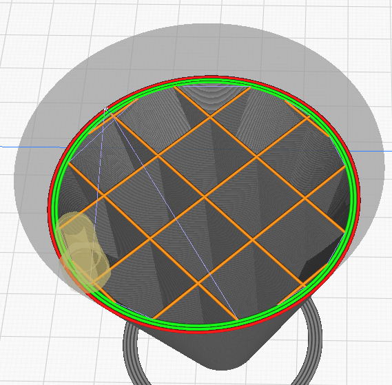
When printing a truncated cone, pay attention to the orientation of the print, as with the cuboid described above. If the small top surface points upwards, the model can be printed hollow.
If the large top surface points upwards, its diameter of 60mm is a little too large for the printer used by the author. Thus, a 5% infill should be used.
Without infill, 2-3 outer layers are definitely sufficient for adequate stability.