Using the G-code preview
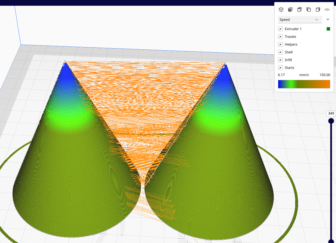
The preview of the G-code has been improved again and again over the course of many Cura updates. While in the past the use of additional software (primarily repetier host) was recommended, today the preview function is very powerful. After the model has been loaded into Cura, placed on the print surface and the desired print parameters have been set, click on “slice” at the bottom right. The model is now cut into individual layers according to the set parameters and the print command is created. Before the generated G-code is sent to the printer (via SD card, USB stick, Wlan), it should be previewed. The “preview” button appears at the top centre after slicing. After a short loading time, the G-code can be analysed. It is helpful to set the colours of the preview to “speed” at the top right. The print speed can now be analysed based on the colours.
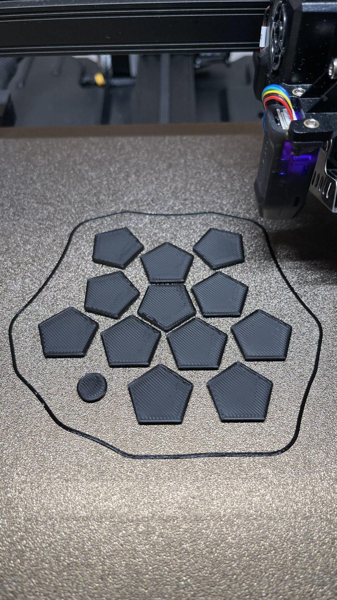
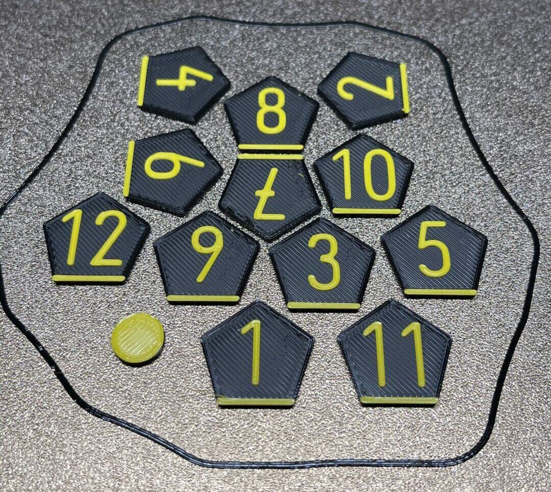
The analysis of individual layers is highly recommended, particularly where braille is concerned. Using the vertical slider on the right-hand side, a section of the model can be hidden so that you really only look at one layer. In this case, pay particular attention to the braille dots. How does the print head move here? Is the outer shell first printed completely and then an attempt made to glue the dot on or does the printer drive a small arc for the dot as desired. It is easy to check that the dots are printed correctly using the preview.

Using different print parameters in one print
It is often necessary to print one and the same model with different print settings in different places. The amount of infill in particular has a great influence on printing time and material consumption.
If you look at the following cuboid, it needs no infill to aid stability. If the model is printed with 3 outer walls, this should be sufficient for teaching purposes.
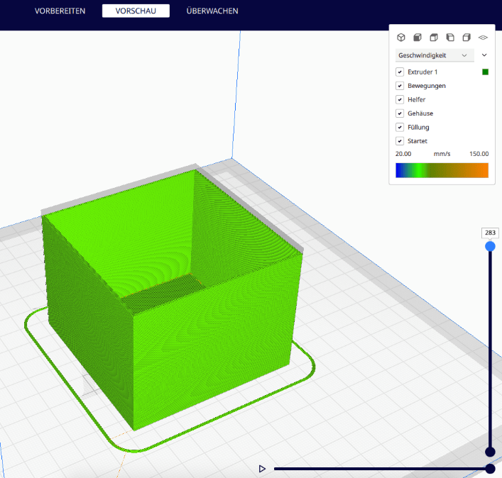
The problem, however, is the top surface, which would be in danger of collapsing due to its size. The solution is to print the model with an infill of about 5% to secure it. However, the printing time would increase from 1:43h to 2:37h. This is where the support blocker tool comes in. By using this, two different degrees of infill can be assigned to the model.
On the left-hand side of the screen in Cura the support blocker can be added. After clicking on the model, a small cuboid appears.
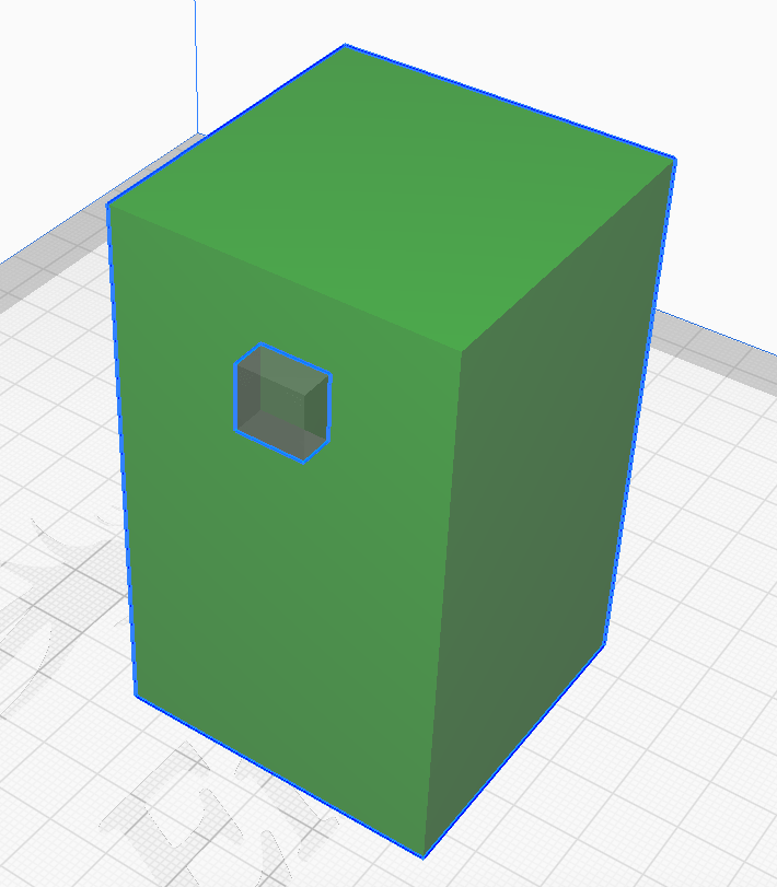
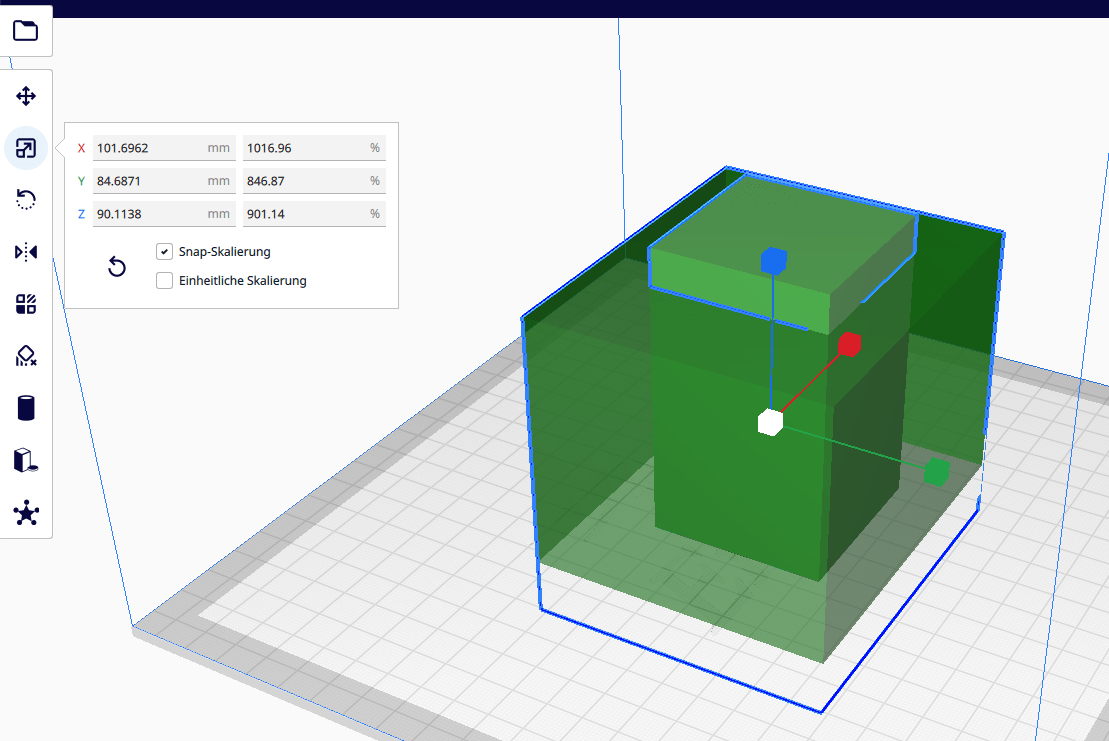
With the usual Cura functions for scaling, the size can be adjusted so that the model is almost entirely covered by the blocker. Only a small part at the top peeks out. This will now be given a different print setting.
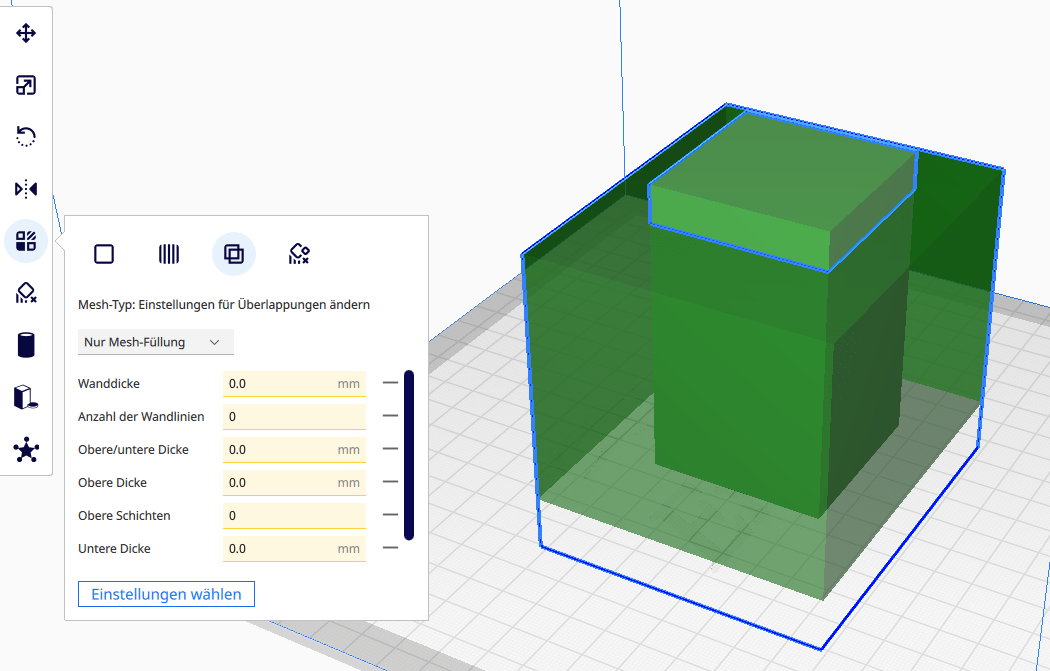
Now click on the support blocker. Then click on the icon for Per model settings on the left and select “Modify setting for overlap”.
For the lower part of the model, i.e. the overlap of the cuboid and the support blocker, the general setting applies that you have set for the print in the menu on the right. So in this case a filling of 0%.
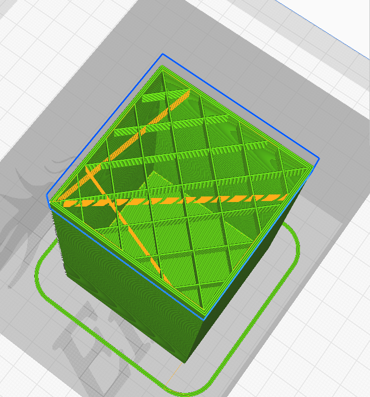
The individual layers of the G-code can now be seen using Preview. You can see that the cuboid is printed hollow here as intended.
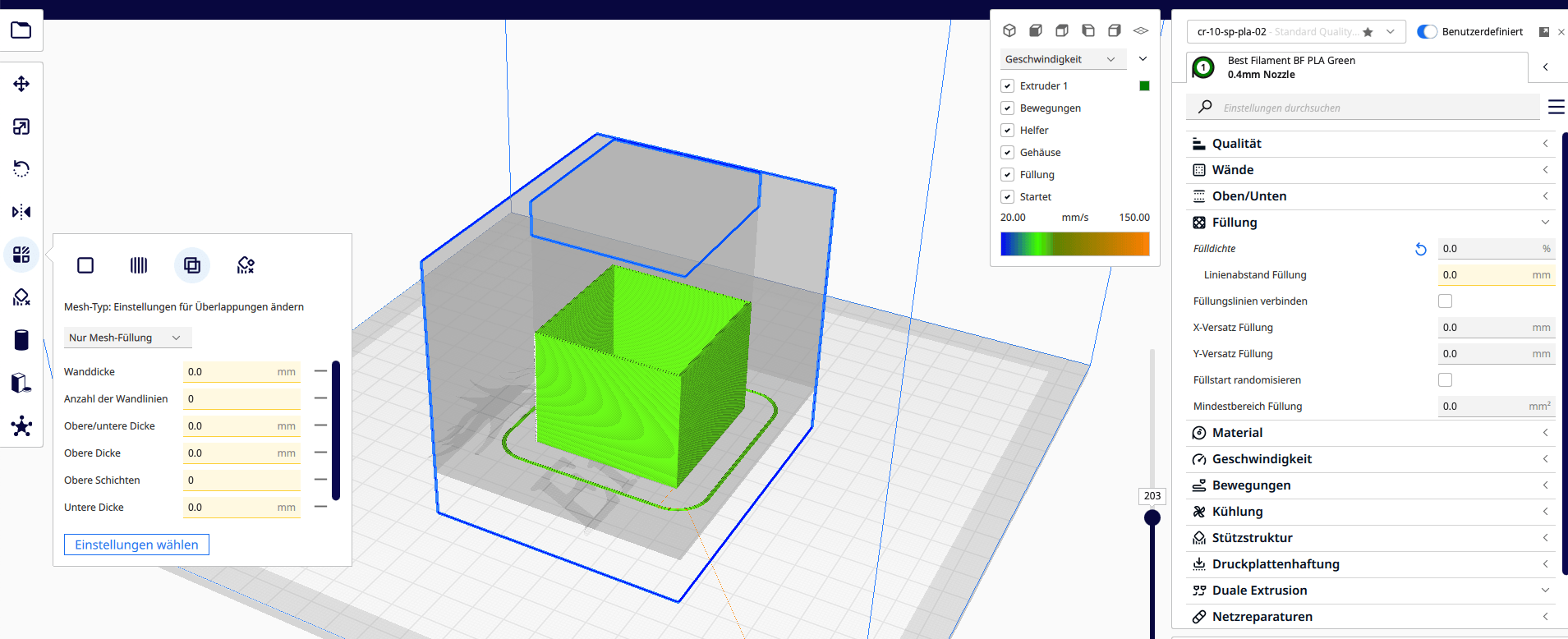
Now click on the upper part of the cuboid. On the left, under “Per model settings”, the filling density for the upper part can now be set. Here, 5% is selected as an example so that the top layer has a nice contact surface. Further print parameters can also be changed here via “Select setting”.

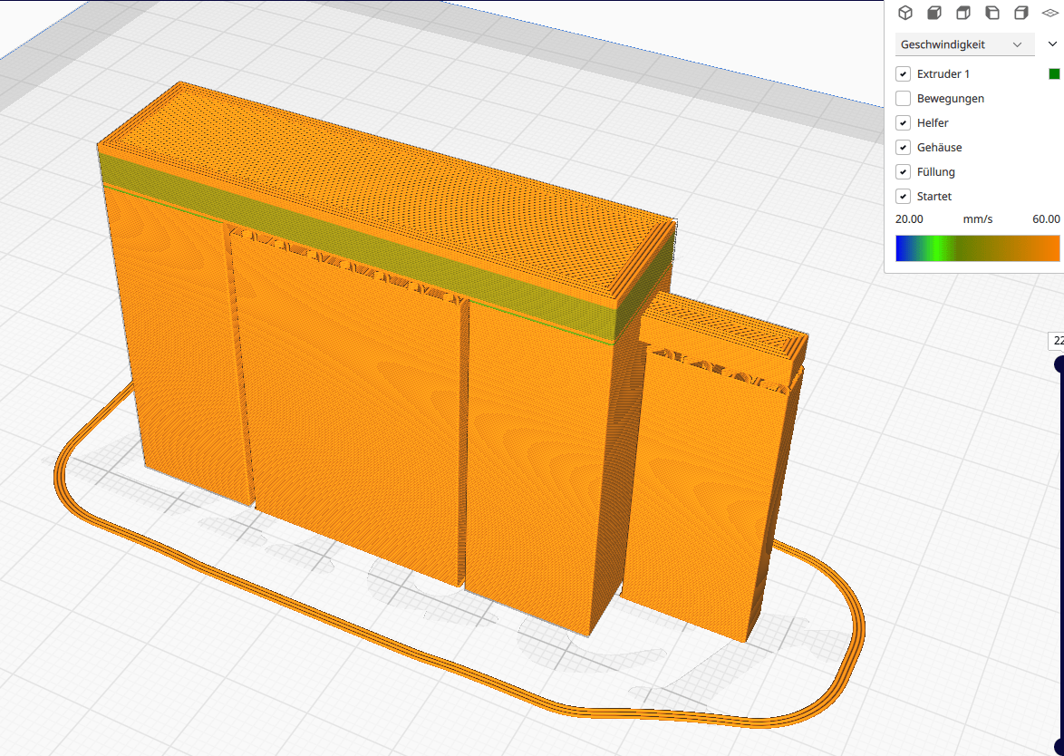
The preview confirms that only the upper part of the box is printed with infill.
Only using support in certain places
If the checkbox “Generate support ” is selected in Cura, support is generated wherever Cura is supposed to generate it according to the set parameters (angle, support placement).
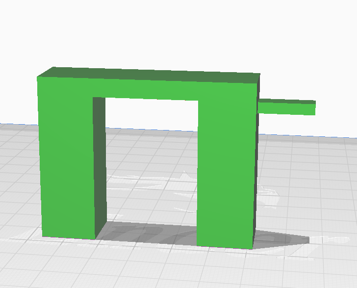
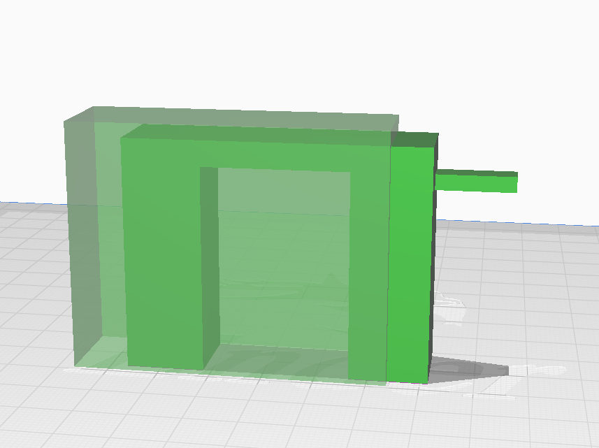
To illustrate this, a model is loaded into Cura which cannot be printed without support. There are two surfaces with a 90° angle to the print bed, which are free-floating and would fall off during printing.
As soon as “Generate support ” is selected, Cura generates it at two points in this model, as expected.
But if you think more carefully about the placement, the support on the left is not absolutely necessary. It is effectively a bridge and has support points on the left and right. It is therefore quite possible to print the model without the left support. In the end a decision has to be made as to whether the quality or the printing time/material consumption should be prioritised.
In this case, the support will only be generated for the overhang on the right, as it is absolutely necessary here. There are two ways to achieve this goal.
- Custom Supports Cylinder Plugin
- Support blocker
Custom Supports Cylinder Plugin
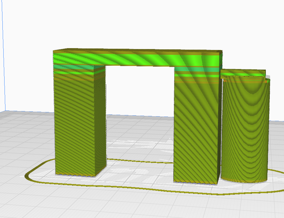
By using this plugin (must be installed in advance via Marketplace – Plugins), a support structure can be placed manually. No support structure is selected in the menu on the right-hand side, but after loading the STL file in Cura the Custom Supports Cylinder plugin is selected on the left-hand side. Now the shape of the custom support can be defined via the menu. In this example the classic cylinder was chosen and the bottom of the right-hand overhang was clicked on with the mouse. By using the tools “move” and “change size” the cylinder was adjusted and Cura automatically converts it with the settings for the support. The preview shows that the cylinder supports the right part of the model during printing.
Support blocker
The second way is via the support blocker, which follows the opposite strategy. Here, “Generate support ” is selected in the menu on the right-hand side. The unwanted support on the left-hand side must now be removed.
To do this, a support blocker is added using the menu on the left-hand side. A small cuboid appears and must be adjusted by moving and scaling so that it covers the left part of the model entirely.
If the model is now sliced, no support is generated in the area where the actual model and the support blocker overlap.

Improve adhesion to the print bed
A number of things have been invented to improve the adhesion of the model to the print bed. Nowadays, a heated print bed is standard on almost every 3D printer. Likewise, most print beds are equipped with a special surface that promises good adhesion. In addition, there are aids that can be applied to the print bed to improve adhesion. 3D Lac has proven to be very effective here.
If these techniques are not sufficient due to the geometry of the model or a filament that is particularly demanding to print, a raft or brim in Cura can be used (right-hand menu in the “build plate adhesion” section). In this case, a grid structure or border is printed under the entire model so that the contact surface on the print bed is increased. This measure improves adhesion, but the raft or brim must be removed from the model afterwards. Unfortunately, this usually leaves traces on the model.


However, it is often not necessary to increase the adhesion of the whole first layer on the print bed. It is the corners in particular that tend to warp in spite of the heated bed and 3D Lac, i.e. they want to lift up slightly from the print bed.
In this case, a selective increase in the contact surface on the print bed is sufficient. The “Tab anti warping” plugin allows you to add tabs to the print bed, which can be positioned as required. The diameter of these tabs can also be adjusted. The height is the same as that of the first layer, which is quite sufficient. After printing, the tabs can be broken off quite easily. If necessary, a cutter knife or sandpaper can also be used.

Test prints for calibration of the printer
If you have a 3D printer that is still quite new or want to process new filaments, it is often necessary to calibrate the printer. The extruder should be calibrated first and there are numerous instructions for this on the internet.
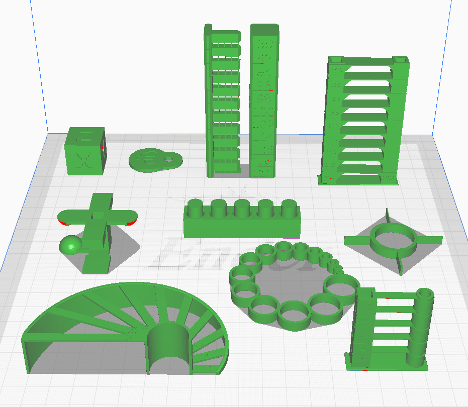
In order to set other parameters such as flow, temperature, retraction etc. correctly, it is necessary to print various test objects. These are printed with different settings to determine the ideal settings for the particular printer. The “calibration shapes” plugin adds a menu with various models for test prints. This saves you from having to search for the right model in a database. In the menu under “Extensions – Part for calibration” you will find a list of test objects. Click on one and it will load directly onto the print bed.
Simple and effective naming of G-code files
It is easy to lose track of files, especially if there are many of them on an SD card, the internal memory or the online memory of a 3D printer and when several 3D printers are used. That is why you are strongly advised to name the files precisely.
An optional plugin can also help here. “Printjob naming” creates the following display at the bottom left of Cura.
The first part of the file name (here CE3) indicates the 3D printer with which the G-code is to be printed. This can be set by the user. As soon as another 3D printer is selected, this part of the filename changes automatically.
The second part of the name is the filename of the STL file. This can be easily changed by clicking in the text field. It can also be useful to add the type of filament to the filename, so that the correct roll of filament can be inserted before the printing process starts.

Multicolour printing by changing the filament
It is possible to switch to different colours of filament during the print process. The procedure, using a plugin in Cura, is described in Article 4.6 Use of colour.